Welcome to the Onshape forum! Ask questions and join in the discussions about everything Onshape.
First time visiting? Here are some places to start:- Looking for a certain topic? Check out the categories filter or use Search (upper right).
- Need support? Ask a question to our Community Support category.
- Please submit support tickets for bugs but you can request improvements in the Product Feedback category.
- Be respectful, on topic and if you see a problem, Flag it.
If you would like to contact our Community Manager personally, feel free to send a private message or an email.
Mates: Geneva Mechanism
 Lewis_Maina
Member Posts: 12 ✭✭
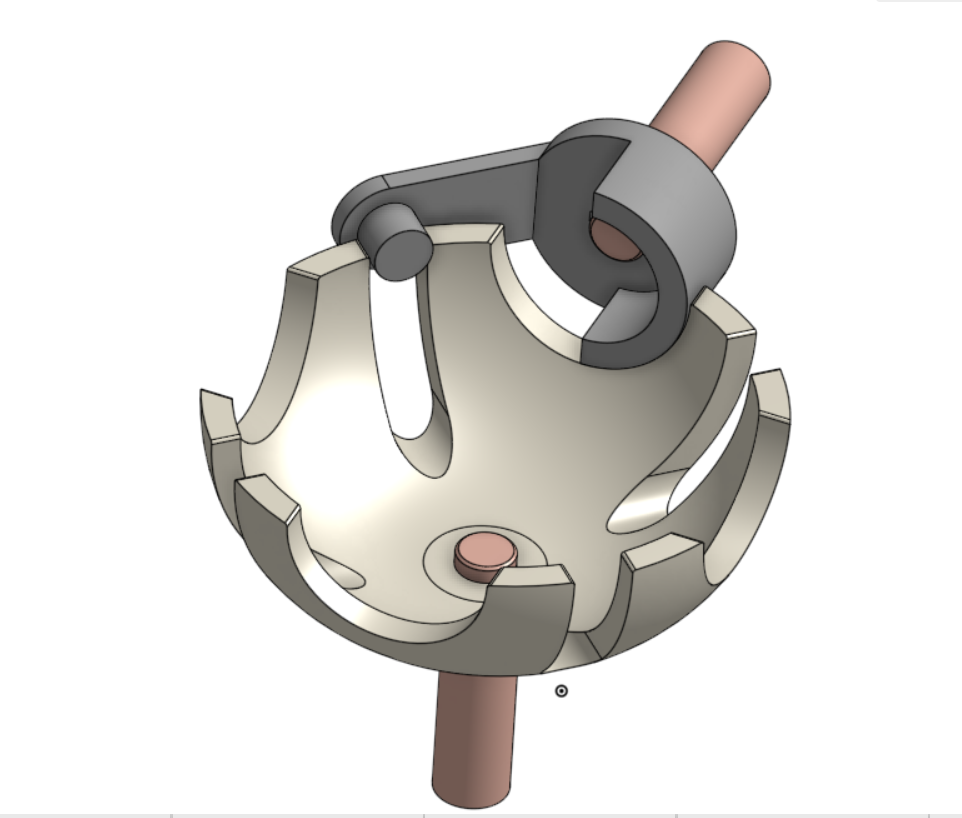
Hi, am trying to simulate Spherical Geneva Mechanism as per the attached Onshape link: https://cad.onshape.com/documents/f93d944f6e541c2b5367d3ea/w/a181825716223b594e276455/e/c718ecc2d5f5ee8409e0bca0?renderMode=0&uiState=62c342f05073a76df8bbfe79
Please help with the steps I should use.
Thanks
Please help with the steps I should use.
Thanks

1


Answers
Learn more about the Gospel of Christ ( Here )
CADSharp - We make custom features and integrated Onshape apps! Learn How to FeatureScript Here 🔴
You should be able to get "one cycle" using a tangent mate but I don't see how you'd make it to keep going.
Otherwise you'd have to create a single "helper" surface describing the follower path and mate it to that but I'm not sure how you'd go about that!
Geneva | Assembly 1 (onshape.com)
Learn more about the Gospel of Christ ( Here )
CADSharp - We make custom features and integrated Onshape apps! Learn How to FeatureScript Here 🔴
I was thinking along the line of a more "direct" mate. This involves more "cheating" (I don't mean that in a bad way at all!) but works great!
I can see how the straight section of sketch2 is 1" long and the "double rad" bump is also 1" long as these each correspond to 1/2 turn of the driver. I guess the .25 bump height is arbitrary and just has to match with the second rack relation. I guess 1in per revolution implies 1/4 in step for a 1/4 turn.
I guess I understand how it works but I just wasn't seeing how you would go about coming up with it but I think I'm starting to see it...
Link the horizontal sliding of the helper part to the input rotation, and then "create" a different degree of freedom that is going to move in steps and drive the output.
I was going to ask how the step work out to be circular segments but I see they are only approximations.
I guess you could make this more accurate by taking a few measurements along one cycle and using a spline instead of circular arks in the helper profile...
The spline and some math would probably more accurate, but this appeared to be accurate enough for the scale of the model.
If there is some additional gearing attached to the output gear, it may begin to show inaccuracies, at which point the sketch that defines the helper surface won't break if you want to modify the crap out of it. (at least that seems to be true with past models I've done this with)
So, you can try some spline math and get it perfect.
Honestly, I did this at lunch one handed eating a pizza over my right shoulder, while drawing on the monitor off my left shoulder, in-between solidworks save/regens trying to get a customer approval drawing out... So, I was all criss-crossed just going for a quick concept, before the Boss peaked around the corner
There is no other way to do this that I am aware of. Since there is no collision detection in Onshape, we need to explicitly define every motion, then link them together with a 'relation' so we only have one mate being animated.
Twitter: @BryanLAGdesign
I tried in Onshape, but it just wouldn't compute. So I had to call on Alnis to put it blender
https://cad.onshape.com/documents/5e3f3f6f4023599ee470e163/w/f02f97b18b159f71a3e48597/e/3169373f38b50f56a14820a6
The helper path is only 1 rotation of the large gear.
So, pattern it out for how many rotations and you get a full animation.
here are 12 rotations