Welcome to the Onshape forum! Ask questions and join in the discussions about everything Onshape.
First time visiting? Here are some places to start:- Looking for a certain topic? Check out the categories filter or use Search (upper right).
- Need support? Ask a question to our Community Support category.
- Please submit support tickets for bugs but you can request improvements in the Product Feedback category.
- Be respectful, on topic and if you see a problem, Flag it.
If you would like to contact our Community Manager personally, feel free to send a private message or an email.
Essential Training Multipart tutorial, stuck on midplane [w/ screenshots]
 daniel_chow
Member Posts: 108 ✭✭✭
Hello everyone,
I'm stuck (again) on the Essential training Multipart studio video tutorial (2:46). In the tutorial, the instructor draws on a midplane but never explains where the midplane is in relation to the R, F, T planes. So I went ahead and drew the model on the TOP plane which made the most sense to me. Later in the video, he extrudes to the mid plane, then mirrors it on the midplane as well, that is where I'm stuck. Why did he use the mid plane? Why didn't he use the top plane and define a distance for the extrusion? Or extrude to and mirror to an offset plane from the top plane? Considering the shape of the object, an offset plane seems to make more sense. Without the midplane, I am not able to continue with the tutorial. If I do, I'm afraid that I'll run into a problem somewhere else down the line. Here is my document shared to public.
Some screenshots: This is the video wit the instructor extruding to the midplane, where is the midplane? How do I transfer my work from the top plane to the mid plane so I can follow the tutorial?
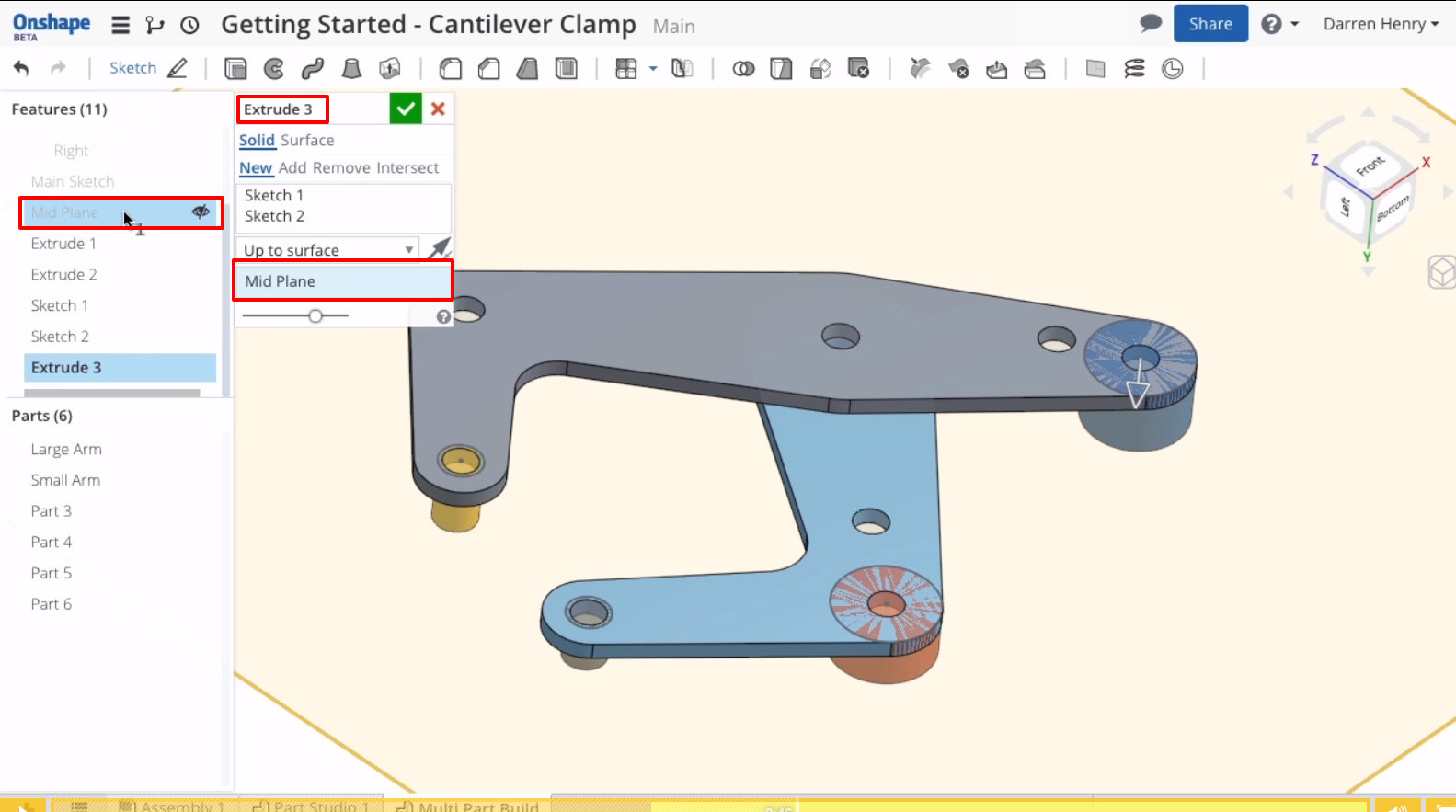
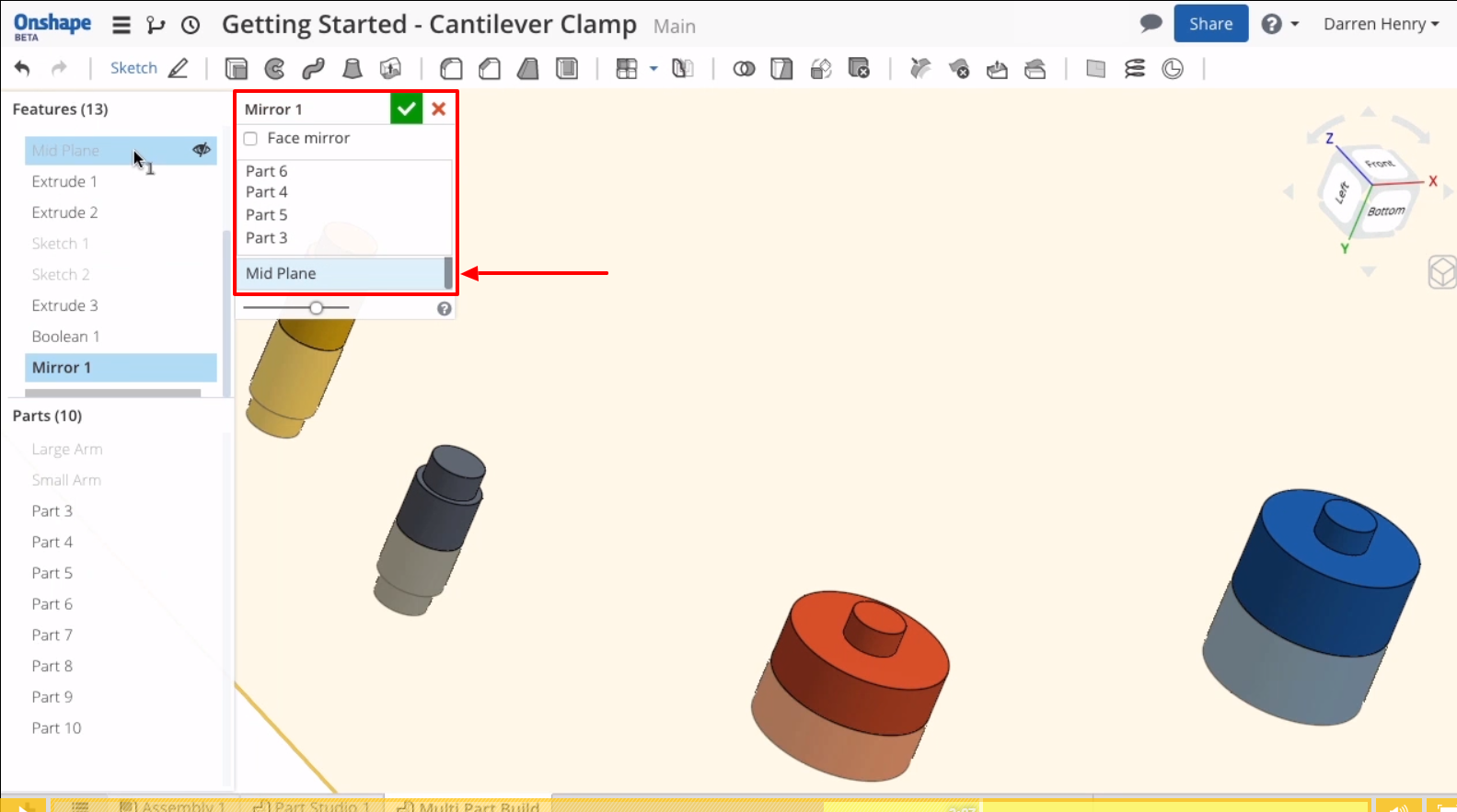
Later the instructor mirrors the pins on the midplane
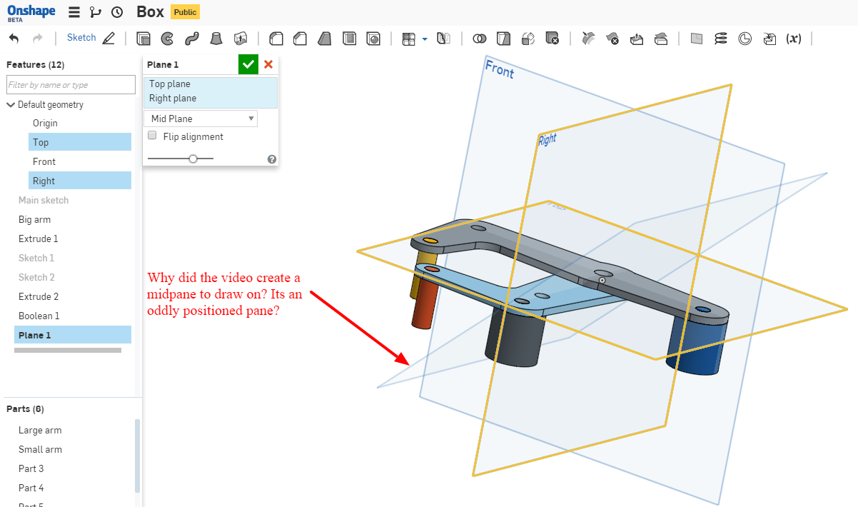
Here is what my reproduction of the object looks like. I drew it on the top plane not knowing how the instructor aligned the mid plane. Why did he even use the mid plane for this?
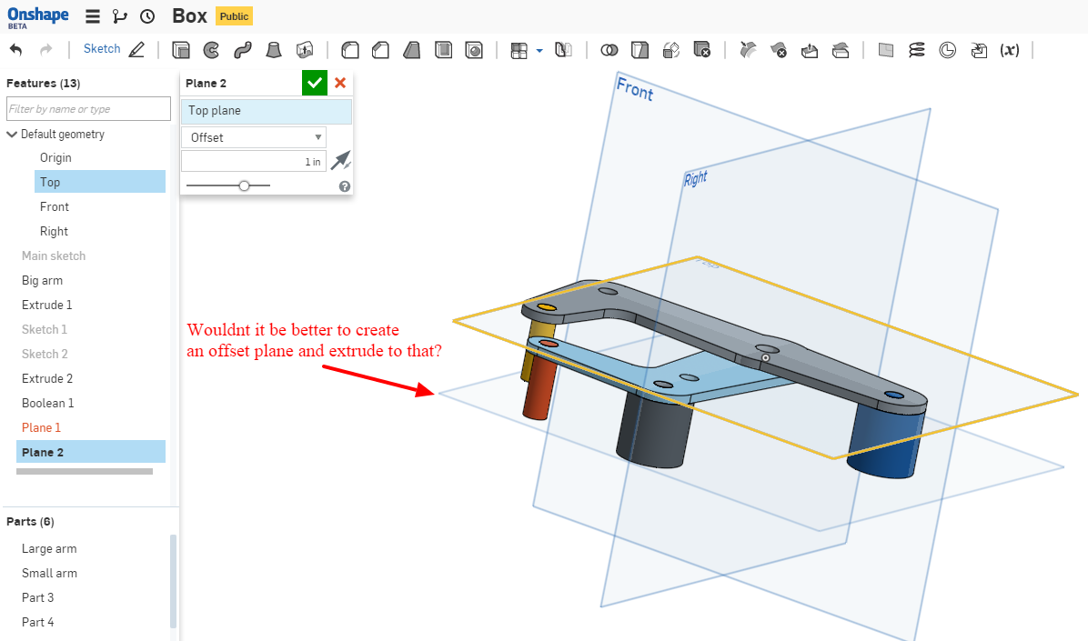
Wouldnt it be better to use an offset plane and extrude to that? Why didn't he just specify a length to extrude?
I'm stuck (again) on the Essential training Multipart studio video tutorial (2:46). In the tutorial, the instructor draws on a midplane but never explains where the midplane is in relation to the R, F, T planes. So I went ahead and drew the model on the TOP plane which made the most sense to me. Later in the video, he extrudes to the mid plane, then mirrors it on the midplane as well, that is where I'm stuck. Why did he use the mid plane? Why didn't he use the top plane and define a distance for the extrusion? Or extrude to and mirror to an offset plane from the top plane? Considering the shape of the object, an offset plane seems to make more sense. Without the midplane, I am not able to continue with the tutorial. If I do, I'm afraid that I'll run into a problem somewhere else down the line. Here is my document shared to public.
Some screenshots: This is the video wit the instructor extruding to the midplane, where is the midplane? How do I transfer my work from the top plane to the mid plane so I can follow the tutorial?

Later the instructor mirrors the pins on the midplane

Here is what my reproduction of the object looks like. I drew it on the top plane not knowing how the instructor aligned the mid plane. Why did he even use the mid plane for this?

Wouldnt it be better to use an offset plane and extrude to that? Why didn't he just specify a length to extrude?

1
Best Answers
-
 nav
Member Posts: 258 ✭✭✭✭
Hi @daniel_chow the mid plane is renamed like this but as you figured out already is an offset plane.
Nicolas Ariza V.
Indaer -- Aircraft Lifecycle Solutions6 -
 andrew_troup
Member, Mentor Posts: 1,585 ✭✭✭✭✭
@daniel_chow
Plane 1 is further down the tree than the Extrude 2 operation from which you are trying to invoke it.
That's why it's depicted in a greyed out font: it doesn't exist, yet.
You need to thumb down a Delorean, travel into the future, and drag that plane as far up the tree as it will go. 5
5 -
 andrew_troup
Member, Mentor Posts: 1,585 ✭✭✭✭✭
@daniel_chow
To answer your earlier question about why a midplane was specified rather than simply an extrusion distance, it's about capturing design intent.
The designer intends that a number of elements will be symmetrical about the midplane of the clamp (particularly the pairs of plates and the ends of the pins). For this to be straightforward and robust and self-evident, that midplane should be an accessible datum.
Ideally it would be one of the three construction planes, eg the Top plane, which could be renamed to "Midplane", and the first act of modelling would be to create an offset plane (representing the interface between the major and minor sideplates)
A careful modeller might choose to define a couple of variables, like "width over major sideplates" and "sideplate thickness", so that the plane offset distance could be calculated using explicit equations, and update correctly if either of those dimensions were changed in future.5
Answers
Indaer -- Aircraft Lifecycle Solutions
Essential training Multipart studio video tutorial (2:46)
I'm trying to extrude down to the this plane 1 / midplane as it shows in the video:
So here is my sketch, you can see that I have a second plane -.5" from the top plane. And the problem is that the pins are not touching the new pane like it is on the video tutorial
So I'm trying to make the pins touch my offset / mid plane, the "Up To Surface" menu item is missing from the Extrude menu, I believe its replaced by "Up To Part", but I still can't make it extrude to Plane 1! Tried everything... help!
[See next message for the screenshot]
Plane 1 is further down the tree than the Extrude 2 operation from which you are trying to invoke it.
That's why it's depicted in a greyed out font: it doesn't exist, yet.
You need to thumb down a Delorean, travel into the future, and drag that plane as far up the tree as it will go.
To answer your earlier question about why a midplane was specified rather than simply an extrusion distance, it's about capturing design intent.
The designer intends that a number of elements will be symmetrical about the midplane of the clamp (particularly the pairs of plates and the ends of the pins). For this to be straightforward and robust and self-evident, that midplane should be an accessible datum.
Ideally it would be one of the three construction planes, eg the Top plane, which could be renamed to "Midplane", and the first act of modelling would be to create an offset plane (representing the interface between the major and minor sideplates)
A careful modeller might choose to define a couple of variables, like "width over major sideplates" and "sideplate thickness", so that the plane offset distance could be calculated using explicit equations, and update correctly if either of those dimensions were changed in future.
As Andrew said, the offset plane has to be stacked ABOVE the extrusion attempt.
Now going to repeat the video a couple of times, let the skills sink in. Thank you again!