Welcome to the Onshape forum! Ask questions and join in the discussions about everything Onshape.
First time visiting? Here are some places to start:- Looking for a certain topic? Check out the categories filter or use Search (upper right).
- Need support? Ask a question to our Community Support category.
- Please submit support tickets for bugs but you can request improvements in the Product Feedback category.
- Be respectful, on topic and if you see a problem, Flag it.
If you would like to contact our Community Manager personally, feel free to send a private message or an email.
Hole tool - Counter sink/bore from exit face/surface
 brian_dodd
Member Posts: 2 EDU
Hi,
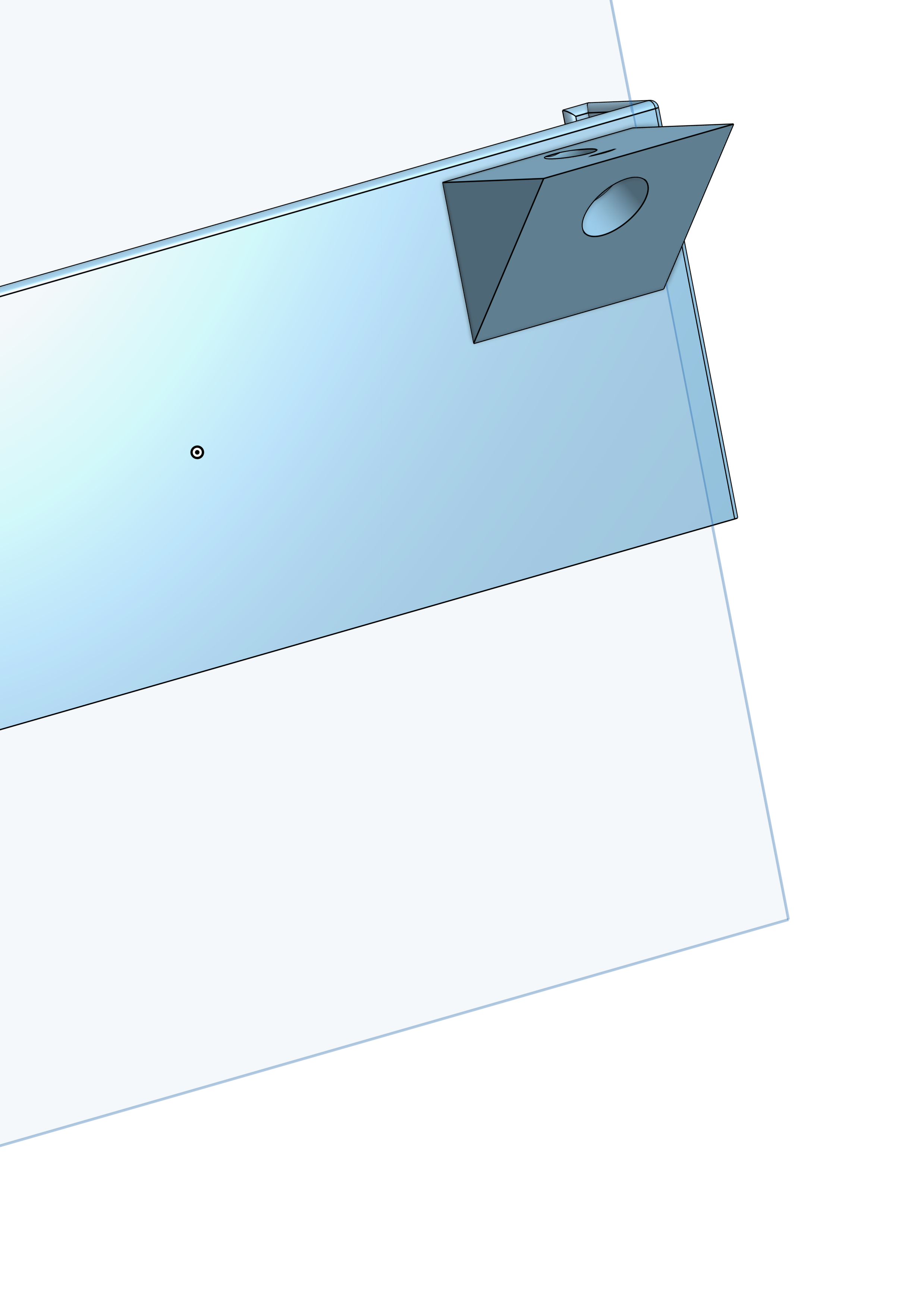
Trying to counterbore at an angle from flat face to angle face. If I sketch hole from flat surface then hole is on wrong angle needed. If I sketch from angle hole for correct hole angle, then angle is correct but bore is at wrong side. Please see photo for example. Is there an option for the hole tool to start from ending face/surface?

0
Answers
https://cad.onshape.com/documents/5ed44ad42884ad9381fdf402/w/ccb0f0d5369a27e732ccc881/e/326995813957f7142d2b7709
is this what you are looking ?
LOOK AT PART STUDIO 1
Then within the mate connector dialog box, under Move, adjust the Z translation to a negative number
then you will have a Mate Connector to use for making the counter bore on the side of the part that you want, at the angle you want
https://cad.onshape.com/documents/5ed44ad42884ad9381fdf402/w/ccb0f0d5369a27e732ccc881/e/326995813957f7142d2b7709
With a few very simple constrained sketches, you could make something where you change one dimension or the other, and everything else will change accordingly. SEE THE GIF ABOVE and PART STUDIO called FLANGE
First off, let’s assume the hole you want, is for bolting or screwing something to that slanted face
Now regarding what’s to be attached to that slanted face — well If I come up with some type of a part with a flange, THEN I MIGHT WANT THE FACE OF THE FLANGE TO DETERMINE WHERE THE HOLE GOES.
So the main jest of the Part Studio called Flange, is about how to transfer the hole location from the slanted flange, to the opposite side, that being the vertical face of Part 1 (left side of Part 1)
And here is how to do that
Now mate connectors are great for when you want to place things at corners, midpoints, or center OF FACE.
But there’s another way to place a mate connector, and that is — ALONG A SEGMENT. And that’s what was used in this part studio called FLANGE, as a segment was used to transfer the hole location on the slanted flange, to the opposite face, that being the vertical left face of Part 1
So starting with PART STUDIO FLANGE - SKETCH 3,
The extruded point looks like a line or segment, but it’s actually classified as a curve.
In this part studio, that curve is on the inside of Part 1, so you’re going to want to set your view to translucent or hide your Part 1 in order to easily place that mate connector
In placing the mate connector at the far end of that curve, you’ll have the first hole location, at the correct angle, and coincident to the left face of Part 1
Now you can use that mate connector to make your counterbore hole. And from there, you could use @Evan_Reese Linear Pattern Plus to locate the other holes. Great tool. I find myself using it more and more !
ON THE OTHER HAND, there may be times where you want to use the vertical face as the guide for where the holes are to be located on the slanted face
If that’s the case, then Matthews way combined with doing some offsets is something you should certainly consider
You could also make a sketch with some points on the vertical face, and use the Multimate Connector FS to place mate connectors at those points with the mate connectors normal to the slanted face. SEE THE GIF BELOW and SEE PART STUDIO 3.. Some may like this method in that it is a more graphical way in that you are seeing the offset dimensions in the sketch window, rather than typing in some offsets into the mate connector dialog box
ONE LAST THING
If you happen to have a Mate Connector hanging out there looking all raggedy and what not as with Part Studio 1, realize that it is not going to make a difference as to counterbore depth, for one thing. It really isn't necessary to have your mate connectors coincident with a face at least IN THIS CASE. So if things are getting cluttered, you just might want the mate hanging out there a bit