Welcome to the Onshape forum! Ask questions and join in the discussions about everything Onshape.
First time visiting? Here are some places to start:- Looking for a certain topic? Check out the categories filter or use Search (upper right).
- Need support? Ask a question to our Community Support category.
- Please submit support tickets for bugs but you can request improvements in the Product Feedback category.
- Be respectful, on topic and if you see a problem, Flag it.
If you would like to contact our Community Manager personally, feel free to send a private message or an email.
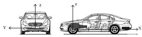
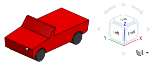
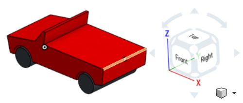
How to work with an automotive standard coordinate system and the view cube display correctly

Answers
-
No - The names of the standard views are not edit-able in onshape. You can, however, create custom named views and name them however you like.0
-
I agree that this can be an issue, and I'd love to address it. The way I see it, for products you typically hold (like a cell phone), you want the cube like the default. For products you get into or on (car, bike, house), you want to do it like the automotive standard. When working on the latter type of product it can cause a surprising amount of confusion.1
-
tim_hess said:No - The names of the standard views are not edit-able in onshape. You can, however, create custom named views and name them however you like.
The custom views do not seem to change the labels on the view cube, as the most prominent representation in the GUI, though, do they? If I share some vehicle model with someone else who is remote, or give a presenation on site, the person will still be confused trying to navigate using the cube, then.Evan_Reese said:I agree that this can be an issue, and I'd love to address it. The way I see it, for products you typically hold (like a cell phone), you want the cube like the default. For products you get into or on (car, bike, house), you want to do it like the automotive standard. When working on the latter type of product it can cause a surprising amount of confusion.Exactly. Maybe there should be a general "Object" and "Vehicle" navigation mode. That would help a lot!The question remains wether this should be on a project, document, assy or part level, since a vehicle would of course consist of parts. It should also affect related drawing views, of course.0 -
Various industries and companies disagree on which axis is up and which axis is pointed towards the "front". There seem to be a lot of aerospace conventions of Z pointing down.

CNC mills and architecture tend to have Z-up:
I always try to have the default view of any part or assembly be the one that is most descriptive. With the ways that the views are labeled, the "front" "left" "right" and "back" don't always correspond to what we might call them. If I have a vehicle pointing towards the "front" plane, then the "right" view is actually looking at what I would think of as the left side of the vehicle (as viewed from the driver/rider/passenger perspective).
I also try to think very carefully where the origin will be so that it's least likely to move around. Some industries want certain coordinates to always be positive, although I think this may be less of an issue as it once was.
The most important thing is to agree on a convention within your company and stick to it.Simon Gatrall | Product Development, Engineering, Design, Onshape | Ex- IDEO, PCH, Unagi, Carbon | LinkedIn
0 -
tim_hess said:No - The names of the standard views are not edit-able in onshape. You can, however, create custom named views and name them however you like.
The custom views do not seem to change the labels on the view cube, as the most prominent representation in the GUI, though, do they? If I share some vehicle model with someone else who is remote, or give a presenation on site, the person will still be confused trying to navigate using the cube, then.Evan_Reese said:I agree that this can be an issue, and I'd love to address it. The way I see it, for products you typically hold (like a cell phone), you want the cube like the default. For products you get into or on (car, bike, house), you want to do it like the automotive standard. When working on the latter type of product it can cause a surprising amount of confusion.Exactly. Maybe there should be a general "Object" and "Vehicle" navigation mode. That would help a lot!The question remains wether this should be on a project, document, assy or part level, since a vehicle would of course consist of parts. It should also affect related drawing views, of course.0 -
The industry conventions regarding coordinate systems are still very important today.While I do not think manufacturing could take a huge advatage from part and assembly design always being done in Z-axis-up, since parts, depending on individual processes, will be reoriented on mills, 3D-Printers and the like anyway, I do see a big issue in architecture, product design and vehicle design, even if certain industries have slightly deviating preferences.Especially when working in networks, with may partners, precise and absolute placement of subassemblies is crucial. Each party repositioning parts relative to something else after file exchange is a source for potential trouble, a time sink, and a bag of fleas to keep track of.If I do a job on a car's dashboard, for example, I need the ergonomics package to be spot on, and I need the latest changes someone else made to the steering column or windshield in some other system to exactly fall in place each day (Onshape even has a handy update import feature for this), while at the same time I must be able to communicate with the software guy who does the eye tracking algorythms, using the proper target coordinates.This does not work overly smooth, when I am designing car parts in a house coordinate system. Also, it is prone to errors, and it gives a much less professional impression, if the CAD system used is not able to follow basic industy conventions none else has had trouble with for decades.All except the gaming industry appear to generally respect the right-hand-3-finger-rule for the XYZ-alignment, no matter what they point it at. That said, and because the axis orientation is the most important part here, automotive and aerospace designers would probably already be much better off, if the labels on views and the navigation cube could simply match the planes they are associated with: Top view was Z view, Front view was X view and left view was Y view, for example, named after the axis they 'look onto'. The same goes for default planes. Even if this would not add any helpful visual information for uninitiated users, it would at least remove the ambiguities from the GUI which cause distraction for everyone.Maybe this coud be solved by a global user default UI setting, and overridden on a document basis?
0 -
I would like to be able to reorient/rename the default views and the origin coordinate system, and store this in part/assembly templates.Until then, it’s always possible to have a helper assembly where you orient your assembly for export with whatever transforms are necessary to have it show up the right way in other tools.
Simon Gatrall | Product Development, Engineering, Design, Onshape | Ex- IDEO, PCH, Unagi, Carbon | LinkedIn
3 -
Another solution would be to allow export (and/or import) to be based on a Mate connector (which is effectively a coordinate system). This might be an easier thing for Onshape to implement.
Here's an improvement request about that.
Here's another about changing the default view cube/coordinate system.Simon Gatrall | Product Development, Engineering, Design, Onshape | Ex- IDEO, PCH, Unagi, Carbon | LinkedIn
2 -
S1mon said:Another solution would be to allow export (and/or import) to be based on a Mate connector (which is effectively a coordinate system). This might be an easier thing for Onshape to implement.
That would certainly be a workaround, though I believe this is not about what is easiest to implement, but easiest to work with. Importing on a mate connector still leaves the most ambiguous view labels in place. So, my favourite solution would be the user defined world coordinate system, be it based on template or settings. We already make similar decisions for things like units, and I can imagine defining the coordinate system in a very similar context.
0 -
I don't know why onshape seems to think they know better than everybody else on why axis conventions are different for each assembly. We just had a major error in a robotics application where the person needing the coordinates of a component in our industry convention from onshape not realizing onshape won't let us use our own coordinate system and caused a major malfunction. Thanks onshape. JUST LET US REDEFINE THE AXES!!!!!!!!!!
1