Welcome to the Onshape forum! Ask questions and join in the discussions about everything Onshape.
First time visiting? Here are some places to start:- Looking for a certain topic? Check out the categories filter or use Search (upper right).
- Need support? Ask a question to our Community Support category.
- Please submit support tickets for bugs but you can request improvements in the Product Feedback category.
- Be respectful, on topic and if you see a problem, Flag it.
If you would like to contact our Community Manager personally, feel free to send a private message or an email.
G³ Constraint for Bézier?
 S1mon
Member Posts: 3,806 PRO
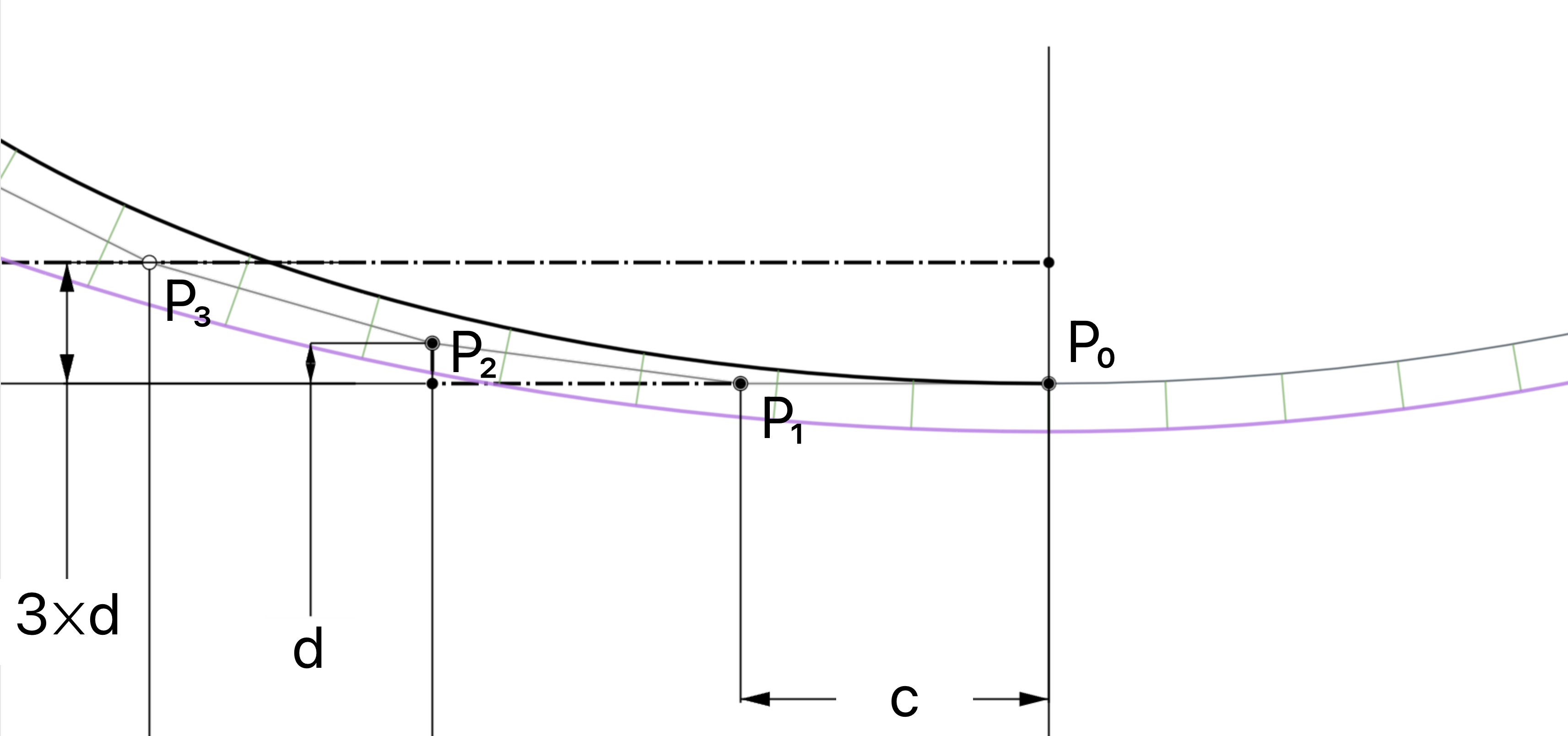
Given a Bézier which is degree n (and in this case n≥3), if I want to make the P₀ end point G² to another curve, I know that there's a simple equation. Let c= distance from P₀ to P₁, d= normal distance of P₂ from the P₀-P₁ vector, and 𝜅 is the curvature of the adjoining curve at the common endpoint. Then d=(n/(n-1))𝜅c². Is there a similar simple equation for a G³ constraint for the P₃ point?
From what I've seen so far, if the adjoining curve has constant curvature (i.e. jolt is 0), then P₃ lies on a line 3d from the P₀-P₁ vector.

From what I've seen so far, if the adjoining curve has constant curvature (i.e. jolt is 0), then P₃ lies on a line 3d from the P₀-P₁ vector.

Simon Gatrall | Product Development Specialist | Open For Work
2
Comments
Simon Gatrall | Product Development Specialist | Open For Work
You can also look how the bridging curve code extracts G2 continuity.
what possible reason do you have to need G3 control? That is going to create one complex curve.
G³ (and sometimes higher) are necessary to do class-A surfacing for industrial design. Rhino, Creo, Alias, Icem, Solidworks, Nx, Catia, etc all have G³ constraints. If you want the zebra stripes to be ≥G², you need the surfaces to be ≥G³.
Simon Gatrall | Product Development Specialist | Open For Work
I have never come across any code to even extract the G2 continuity let alone the jolt. Hopefully someone on here has and can supply it to us.
I think you need to establish some sort of rules for your requirement.
Another option is to import a curve from one of the other systems and import it and analyze how that cad engine decided to generate that curve. If it does not import as a BSpline curve and needs to be analyzed using evApproximateBSplineCurve, then export it as a step file(just the curve) and you can read the b spline curve data in the step file by opening it with notepad. Then reverse engineer it somehow to determine how they determine where the control points are placed.
If you don't have access to any of those cad systems, which i dont either, then hopefully someone can give you a step file with the curves you need to reverse engineer it.
    // using k = ((degree - 1) / degree) * h / |t| ^ 2, where k is curvature, t is tangent vector, h is the minimum distance
    // from the next control point to the extension of tangent direction
    var distance = (degree / (degree - 1)) * curvatureFrame.curvature * speed * speed;
Below is from Thomas W Sederberg's Computer Aided Geometric Design (a free-to-download 273 page book which is a great reference on Béziers, B-Splines, etc). Assuming that we're using non-rational Béziers, you can ignore the first term in the 2.13 equation, and that's the same as what's in the Bridging curve code. "speed" is a in the diagram below, "distance" is h. The Bridging curve equation has just solved 2.13 for h instead of k.
Simon Gatrall | Product Development Specialist | Open For Work
Here's a pass at something similar to your example:
https://help.autodesk.com/view/ALIAS/2024/ENU/?guid=continuity-g0-g1-g2-g3 (Look at the section "Deep dive: G3 and G4 continuity")
Simon Gatrall | Product Development Specialist | Open For Work
Simon Gatrall | Product Development Specialist | Open For Work