Welcome to the Onshape forum! Ask questions and join in the discussions about everything Onshape.
First time visiting? Here are some places to start:- Looking for a certain topic? Check out the categories filter or use Search (upper right).
- Need support? Ask a question to our Community Support category.
- Please submit support tickets for bugs but you can request improvements in the Product Feedback category.
- Be respectful, on topic and if you see a problem, Flag it.
If you would like to contact our Community Manager personally, feel free to send a private message or an email.
Threading Shafts and Holes with Supressable Modeled Threads
 john_hauck
Member Posts: 54 PRO
I would cherish a bit of advice on threads again.
My goal is for a Part Studio to use the Configuration Panel to turn threads on and off.


The only work-arounds I have are:
My goal is for a Part Studio to use the Configuration Panel to turn threads on and off.
- When off, the dimensions should be as-machined (before cutting the threads) - and supported by Drawing hole/thread callouts.
- When on, the correct threads should be modeled.
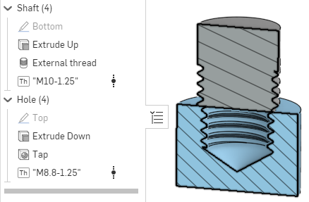
- "External Thread" tool
- "Thread Creator" FeatureScript by Dave Cowden
- Configure suppression with the Configuration Panel
- "Hole" tool
- "Thread Creator" FeatureScript by Dave Cowden


The only work-arounds I have are:
- Use a move-face option with some magic distance when enabling internal threads.
- Use "Threads" FeatureScript by Julia Schatz - which is less configurable.
0
Comments
Have you tried the "threadlabs" featurescript?
I like that it offers options for different thread representations so all you should have to do is configure the one feature.
https://cad.onshape.com/documents/5c0528b62c1fbb13a2a0e739/v/f86229e7f586f8517a2068a9/e/7cbb452d4d5e963a034ce616?jumpToIndex=2851&showReturnToWorkspaceLink=true
The Onsherpa | Reach peak Onshape productivity
www.theonsherpa.com
Thank you your replies.
I did indeed try Thread Lab and found that for internal holes created by the Tap feature, it too makes the threads too small.
Here is an updated version of the document that allows switching between Thread Creator and Thread Labs.
https://cad.onshape.com/documents/8709f9d60bec3de1edf2665d/w/d5b45dd621951389b8276062/e/8d9e6e8fe5b7d91b4755b349?configuration=List_r0zfKFIEfl5JGj=Thread_Lab&renderMode=0&rightPanel=configPanel&uiState=645298dd3d600e5acab3915a
I think the simple solution is to just configure the "tap" hole diameter to 10mm for the threaded configurations (and leave it at the standard tap diameter in the unthreaded configuration):
https://cad.onshape.com/documents/cc32ccff9e99836af3879e82/w/4e553a8c737282cb1e3ac5cf/e/9b51577bc9d1a293c1f38cd0
As a side note, if the part is going to be drilled and tapped using "conventional" machining then there might not be much value in having the actual thread modeled and this should be used sparingly due to the performance impacts... The main application is for 3D printing (or I guess sometimes for producing "illustrations" like rendering of customer documentation).
When modeling without threads, I just use the Hole feature, and set it to "tapped" and specifying the thread. It creates a hole that is useful for the tapping operation. A drawing of the part correctly calls out the thread. That means the Hole feature "marked" the hole in the geometry with the appropriate thread size and pitch (somehow). This is good... very good. Kudos OnShape.
So my wish would be that to model the threads, the FeatureScripts should just read this information from the geometry (like the drawing do) and then do their thing. They should not even ask what thread or pitch to use, since that is already there.
I really don't want to write this myself as it seems like an obvious thing that someone already tackled.
Finally, why do I care about modeling threads? Well, it helps not just with 3D printing, but also with checking the fit between threaded holes and shafts. If there is a mis-match, it is easy to spot. And like you mentioned, it also helps make renders much more realistic... and who would dare stand in the way of more realism in their renders?!
Cheers and thanks for chiming in and reading this far in my rant.
I'm also not sure what it would take for a feature like Threadlabs to set the size of the hole!
Hopefully @antlu65 see this and chime in!
I’m going to start over and explain how I deal with threads in the hopes that this will explain my feature requests.
Here is an OnShape documument that helps explain the situation.
Non-modeled external threads
The built-in feature tool “External Thread” is what I want to use for the simple fact that is being supported by OnShape.
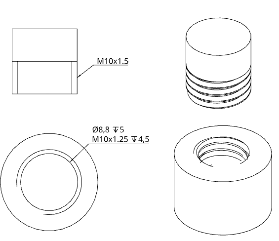
It requires that the cylinder diameter matches the thread’s outer diameter. So, for an M10 thread, the cylinder’s diameter should be 10mm. The External Thread sets up the model so that it appears on drawings, showing both the outer and inner diameters of the threaded area. The drawing’s Hole/Thread callout automatically displays the thread information on the drawing as well. This really is all that is needed to send a part to be manufactured by a machine shop.
Modeled external threads
Since all the thread information is already in the model, it would make sense if the thread geometry would be driven by that information.
If I change the thread pitch in “External thread” then the threads modeled would change as well.
I could then use the “Configuration panel” to define whether I wanted modeled threads or not (by suppressing ThreadLab). Using two configurations of the part in the same drawing, I could make something like this:
However, you will notice the callout created by ThreadLab 0.3 is inconsistent.
Requests for External threads in ThreadLab 0.3:
Non-modeled internal threads
The built-in feature tool “Hole” is what I want to use for the simple fact that is being supported by OnShape.
Select tapped and specify the thread, pitch, thread depth, hole bottom, and tap clearance. The Hole sets up the model so that it appears on drawings, showing both the outer and inner diameters of the threaded area. The drawing’s Hole/Thread callout automatically displays the thread information on the drawing as well. Specifically, drill an 8.8mm diameter hole, 5mm deep, and then thread it as M10x1.25. This really is all that is needed to send a part to be manufactured by a machine shop.
Modeled internal threads
Since all the thread information is already in the model, it would make sense if the thread geometry would be driven by that information.
If I change the thread pitch in “Hole” then the threads modeled would change as well.
I could then use the “Configuration panel” to define whether I wanted modeled threads or not (by suppressing ThreadLab). Using two configurations of the part in the same drawing, I could make something like this:
However, you will notice the callout created by ThreadLab 0.3 is incorrect, because it is driven by the diameter of the hole, and not the information added by the “Hole” feature.
Request for internal threads in ThreadLab 0.3:
- Add an option to be driven by the Hole data of the part. This means the threading operation will remove material, not add it. It also means performing partial threading based upon the configuration used to make the Hole.
I hope I have been clear and maybe even compelling.