Welcome to the Onshape forum! Ask questions and join in the discussions about everything Onshape.
First time visiting? Here are some places to start:- Looking for a certain topic? Check out the categories filter or use Search (upper right).
- Need support? Ask a question to our Community Support category.
- Please submit support tickets for bugs but you can request improvements in the Product Feedback category.
- Be respectful, on topic and if you see a problem, Flag it.
If you would like to contact our Community Manager personally, feel free to send a private message or an email.
Boundary surface: A-B spline surface could not be created with the given definition
 brendan_mitchell525
Member Posts: 6 ✭
Hi all!
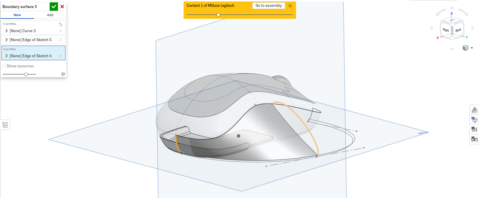
I'm dipping my toes in the water with surface modeling by designing an ergonomic attachment for my mouse. I have some profiles sketched out that I want to use to make a boundary surface, but I'm getting errors that I can't find documented anywhere. The error is:
A-B spline surface could not be created with the given definition
The error shows up when I try to select the final edge of the boundary surface as shown here:


I've done the same thing with (seemingly) similar areas and gotten exactly the result I want. Any ideas?
Here's the CAD:
https://cad.onshape.com/documents/3bc0a79571b63a8b30eb7fb2/w/29ba987c49223e396f417b1f/e/98aedc8fc8f32dd1c32ea235
I'm dipping my toes in the water with surface modeling by designing an ergonomic attachment for my mouse. I have some profiles sketched out that I want to use to make a boundary surface, but I'm getting errors that I can't find documented anywhere. The error is:
A-B spline surface could not be created with the given definition
The error shows up when I try to select the final edge of the boundary surface as shown here:


I've done the same thing with (seemingly) similar areas and gotten exactly the result I want. Any ideas?
Here's the CAD:
https://cad.onshape.com/documents/3bc0a79571b63a8b30eb7fb2/w/29ba987c49223e396f417b1f/e/98aedc8fc8f32dd1c32ea235
0
Answers
Simon Gatrall | Product Development, Engineering, Design, Onshape | Ex- IDEO, PCH, Unagi, Carbon | LinkedIn
https://cad.onshape.com/documents/2d2cf3d0b732941e8f78c63a/w/55b6fa827615a9b0b8bfddba/e/ddc7dc09dd6fc3ab239d09c2
The Onsherpa | Reach peak Onshape productivity
www.theonsherpa.com
Simon Gatrall | Product Development, Engineering, Design, Onshape | Ex- IDEO, PCH, Unagi, Carbon | LinkedIn