Welcome to the Onshape forum! Ask questions and join in the discussions about everything Onshape.

First time visiting? Here are some places to start:
  1. Looking for a certain topic? Check out the categories filter or use Search (upper right).
  2. Need support? Ask a question to our Community Support category.
  3. Please submit support tickets for bugs but you can request improvements in the Product Feedback category.
  4. Be respectful, on topic and if you see a problem, Flag it.

If you would like to contact our Community Manager personally, feel free to send a private message or an email.

assembly pattern breaks original mates.


If I pattern a mated part, the original mates fail. 
how come.? anyone else experienced the same thing? 
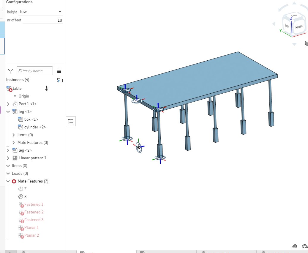
simplified example: Untitled document | table (onshape.com)


Answers

  • rick_randallrick_randall Member Posts: 322 ✭✭✭
    Try this - edit linear pattern & under direction pick long edge of flat rectangle (highlight direction box & click on edge in graphic window), you may need to reverse the direction if the result is not what you want. You can use edges of the model to define directions. I got your model to work by deleting x & z mate connectors and making the above edits. Hope this helps.
  • steven_van_luchene848steven_van_luchene848 Member Posts: 122 PRO
    Hi Rick. 

    thanks fot the answer, Indeed this works. But I actually need the x&z mates... they uniquely define the position of the assembly / foot. I just don't see why patterning a constrained element should break the original constraints... The aim is to automate the design os a certain product through configurations. 
    This however prevents from doing so, because then must manually position the first element before applying the pattern. I havent found another way of instancing elements in an assembly other than patterning. I wonder if there is a workaround as I can't really imagine I'm the first one with this kind of challenge. 
  • rick_randallrick_randall Member Posts: 322 ✭✭✭
    I have had similar type issues ( maybe I'm talking apples & oranges here) and I'm not sure if will help, but you might try this methodology  - create one configuration that works, then add more features that define 2nd config. If errors flag on one or more configs. go to feature tree and right click on "red" features, choose "configure suppression" ,select proper config. list from flyout. Then go to config. list,  and check or uncheck the appropriate boxes (this could be a long list depending on the complexity of your model). I use this approach to solve relatively complex part configurations that have radically different end shapes.(I'm thinking suppressing X&Z mates - you can always unsuppress in different configs. - that way they show up where you need them). There seems to be no limit to the complexity that can be achieved in configs.  Without knowing your exact intent, it is impossible to give you a "perfect" answer, but you might consider this method and modify it to give you what you're after.

    If this doesn't describe your problem, please disregard.   Best luck,
     

  • rick_randallrick_randall Member Posts: 322 ✭✭✭
    And two hours later, the new update comes out with rigid parts in assemblies - you might want study that one real good.
  • eric_pestyeric_pesty Member Posts: 1,875 PRO
    I might be missing something but why not just configure the length of the legs so you don't need the "planar" mates in the assembly?
    You also don't need to explicitly define mate connectors everywhere (for example at the end of the legs). 

    https://cad.onshape.com/documents/b8da0f74fb0555c70f580c80/w/9999557e0f4aa83e07dc9f3e/e/42d5b43bb5075efa11639671


  • rick_randallrick_randall Member Posts: 322 ✭✭✭
    I agree with eric_pesty on this one. We all have to remind ourselves to keep it simple, don't we.
  • rick_randallrick_randall Member Posts: 322 ✭✭✭
    Hi Rick. 

    thanks fot the answer, Indeed this works. But I actually need the x&z mates... they uniquely define the position of the assembly / foot. I just don't see why patterning a constrained element should break the original constraints... The aim is to automate the design os a certain product through configurations. 
    This however prevents from doing so, because then must manually position the first element before applying the pattern. I havent found another way of instancing elements in an assembly other than patterning. I wonder if there is a workaround as I can't really imagine I'm the first one with this kind of challenge. 

    Just curious have you used the "replicate" command much - it doesn't work exactly like a linear pattern , but can be useful for quickly populating  an assembly with multiples of the same part, as long as you have some kind of reference geometry or sketch entities. I'm pretty sure this would work - but not sure if it is a time saver for you, (you would probably have to create and configure a sketch in the table top part - then use sketch points to constrain the first leg in the assembly, then "replicate" all other leg instances). I like to use replicate as much as possible - it keeps assemblies simple, but is by no means the only way to get results. Remember there is no right or wrong way to do things, only fast or slow ways.
  • rick_randallrick_randall Member Posts: 322 ✭✭✭
    Back to the original post - is this what you were after
    just used 2nd direction in the linear pattern, then mated one leg after that. If you are going to configure different leg spacing I suggest making variables for the distances and configuring those variables in the config. table. Wow this went down a rabbit hole. Hope this helps
  • steven_van_luchene848steven_van_luchene848 Member Posts: 122 PRO
    Hi Rick. 

    thanks fot the answer, Indeed this works. But I actually need the x&z mates... they uniquely define the position of the assembly / foot. I just don't see why patterning a constrained element should break the original constraints... The aim is to automate the design os a certain product through configurations. 
    This however prevents from doing so, because then must manually position the first element before applying the pattern. I havent found another way of instancing elements in an assembly other than patterning. I wonder if there is a workaround as I can't really imagine I'm the first one with this kind of challenge. 

    Just curious have you used the "replicate" command much - it doesn't work exactly like a linear pattern , but can be useful for quickly populating  an assembly with multiples of the same part, as long as you have some kind of reference geometry or sketch entities. I'm pretty sure this would work - but not sure if it is a time saver for you, (you would probably have to create and configure a sketch in the table top part - then use sketch points to constrain the first leg in the assembly, then "replicate" all other leg instances). I like to use replicate as much as possible - it keeps assemblies simple, but is by no means the only way to get results. Remember there is no right or wrong way to do things, only fast or slow ways.
    Yes. I did at one time (just to be able to account for a yet unknow number of instances...) but it only works in a plane  and on features (eg hole features) There is a feature request to be able to replicate to mate connectors. which would allow for some kind of "skeleton model" approach with a "dummy part" containing all the mate connector defined in a part studio (which allows for far more control eg by using custom  featurescript)  and instancing to those mate connectors in the assembly. So indeed, if was to make a dummy part with eg hole features to define positions, this approach works. 


  • steven_van_luchene848steven_van_luchene848 Member Posts: 122 PRO
    I might be missing something but why not just configure the length of the legs so you don't need the "planar" mates in the assembly?
    You also don't need to explicitly define mate connectors everywhere (for example at the end of the legs). 

    https://cad.onshape.com/documents/b8da0f74fb0555c70f580c80/w/9999557e0f4aa83e07dc9f3e/e/42d5b43bb5075efa11639671


    Indeed seems logical. i'll try that. thanks! 
  • steven_van_luchene848steven_van_luchene848 Member Posts: 122 PRO
    And two hours later, the new update comes out with rigid parts in assemblies - you might want study that one real good.
    indeed this seems like a huge improvement. 
    will be looking into this. 
Sign In or Register to comment.