Welcome to the Onshape forum! Ask questions and join in the discussions about everything Onshape.
First time visiting? Here are some places to start:- Looking for a certain topic? Check out the categories filter or use Search (upper right).
- Need support? Ask a question to our Community Support category.
- Please submit support tickets for bugs but you can request improvements in the Product Feedback category.
- Be respectful, on topic and if you see a problem, Flag it.
If you would like to contact our Community Manager personally, feel free to send a private message or an email.
Need Better Modeling Strategy
 robert_goldrich
Member Posts: 4 ✭
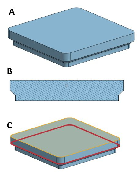
I am trying to model a "roll-my-own" grid storage system, not unlike Gridfinity or others.

Illustration A shows the shape of my container -- except that it is solid, and I want a shell of that shape (i.e. by "imploding" the top face). Illustration B shows the basic cross section, and C shows the error coming from the shell tool. I'm sure this is not a bug from Onshape, but a problematic modeling strategy on my part.
Here is a link to the model in Onshape. Any modeling tips will be greatly appreciated. Many thanks in advance! -Rob
0
Best Answers
-
 john_lopez363
Member Posts: 140 ✭✭✭
@robert_goldrich... not sure why but the problem is being caused by the "Chamfer". Change your order of operation, add the Chamfers after the Shell. And add the inside and outside Chamfers separately.
EDIT: You'll need to adjust the distance of inside Chamfer some (i used 2.5mm here). !
!
0 -
 S1mon
Member Posts: 3,992 PRO
There are many ways to solve this kind of issue. One would be to manually create the shell by offsetting the surfaces in two sets, and doing a mutual trim and then cutting out the inside with a split part. That would take a lot of face selections. The way I ended up doing it was to split the part (temporarily) into two parts, shell each of them, boolean union them back together, and removed a face so that you end up with a roughly constant wall.
Simon Gatrall | Product Development, Engineering, Design, Onshape | Ex- IDEO, PCH, Unagi, Carbon | LinkedIn
0 -
 wayne_sauder
Member, csevp Posts: 641 PRO
As you can see there are many ways you could get this done.
In case you are still trying to figure out why that shell command doesn't work. Try reducing the wall thickness until it does. I think it is around .5 mm that it does work. This indicates that a thicker wall tries to create A. a wall thickness that is not uniform or B. a non-manifold geometry. If you study these 2 subjects in depth the reason the shell tool gives an error makes some sense. I'm not quite sure what wall thickness you are going for but as is shown by the various examples there are ways to force this however there are 2 things that may show up non-uniform wall thickness and crazy things going on in the corners.
A couple of things that would make the shell command work.
All corner fillets should have a radius larger than the wall thickness.
The part that overhangs the chamfer needs to overhang by a dimension greater than the wall thickness.0
Answers
EDIT: You'll need to adjust the distance of inside Chamfer some (i used 2.5mm here).
Simon Gatrall | Product Development, Engineering, Design, Onshape | Ex- IDEO, PCH, Unagi, Carbon | LinkedIn
The way I thought would be better is to explicitly define the wall profile, both inside and outside, via sketch. Then I perform a sweep for the wall and then add on a floor. I think the results look much better:
Here's the doc: https://cad.onshape.com/documents/f4ee08d6980c2b0def0ee080/w/71443ae1dfc381b4bf6feb35/e/cb5fde0eca06ddd6c5ad5cb6
https://cad.onshape.com/documents/e74770d3d7183f4f768ed54c/w/e558b559e0648d8bf851597b/e/b217bdf7f3faf62a2ff21392
https://forum.onshape.com/discussion/23776/improvements-to-onshape-april-26th-2024/p1?wvideo=z3vs8dhnjf
In case you are still trying to figure out why that shell command doesn't work. Try reducing the wall thickness until it does. I think it is around .5 mm that it does work. This indicates that a thicker wall tries to create A. a wall thickness that is not uniform or B. a non-manifold geometry. If you study these 2 subjects in depth the reason the shell tool gives an error makes some sense. I'm not quite sure what wall thickness you are going for but as is shown by the various examples there are ways to force this however there are 2 things that may show up non-uniform wall thickness and crazy things going on in the corners.
A couple of things that would make the shell command work.
All corner fillets should have a radius larger than the wall thickness.
The part that overhangs the chamfer needs to overhang by a dimension greater than the wall thickness.
https://cad.onshape.com/documents/ef11856685bcfc2a5bbbb116/w/8a7456388332f82135a94400/e/595474670b0b2df6b4d0bb12
In the cell experiment, I used Neil's suggestion of a thin sweep. (Probably the best option.)
In the copy of the cell experiment, I got the shell command to work by increasing the size in Sketch 2 by a little (I realize this might not be an option, I am just showing what it takes to make it work).
If you allow me to, might I suggest that the grid be made in the same parts studio and be made to fit exactly by using an offset from the bin?
Simon Gatrall | Product Development, Engineering, Design, Onshape | Ex- IDEO, PCH, Unagi, Carbon | LinkedIn
I will need a day or two to digest this, but I so appreciate everyone taking the time to provide me with complete, competent, answers.
I hope I get to pay it back or forward in the future!
Rob