Welcome to the Onshape forum! Ask questions and join in the discussions about everything Onshape.

First time visiting? Here are some places to start:
  1. Looking for a certain topic? Check out the categories filter or use Search (upper right).
  2. Need support? Ask a question to our Community Support category.
  3. Please submit support tickets for bugs but you can request improvements in the Product Feedback category.
  4. Be respectful, on topic and if you see a problem, Flag it.

If you would like to contact our Community Manager personally, feel free to send a private message or an email.

How am I supposed to do this without a hinge mate?

william_lacey140william_lacey140 Member Posts: 19
Coming from a SolidWorks background, this was easily achieved with a hinge mate that had limits on how much it opened. I know I can mate the connectors with limits, but none of the connectors end up being aligned with each other in either the closed or open position. From my understanding, I cannot realign a mate connector with another part. So it's hard to know what pair of connectors to use for the limit and what the angle limits are. There are 7 different hinges in this assembly. How would you do this?
Best Answer

  • martin_kopplowmartin_kopplow Member Posts: 513 PRO
    edited July 7 Answer ✓
    For more clarification, the total angular travel distance for the cup hinge is 165 degrees. There is no singular point of rotation to define this.
    Hi William,
    I guess that is exactly what can be achieved using the parallel mate. In my above sample I applied revolute mates to all the joints, with no limits set, and applied only one single parallel mate to the two mounting plates to control the overall angle of the mechanism and deliberately limited the angle at 25 or something within the parallel mate, just to demo, for I used less joints and won't get your 165° at all. I'm sure this works with your model, too. The parallel mate does not require an explicit point of rotation to be set. Leave all other limits blank, only fill in the max. and min. Z-Angle.


Answers

  • martin_kopplowmartin_kopplow Member Posts: 513 PRO
    edited July 6
    I would first place explicit mate connectors on the holes in each part I want to use. If possible, I'd do that in their part studios, else, I'd isolate the individual parts in the assembly to precisely define the mate connectors locations I need. It might be possible to use implicit mates connectors, but explicit ones provide a little more oversight and control in case there is play between the parts: Use the 'between' option to align centers. Then, I'd use the revolute mate on these mate connectors and only limit one of them all to define the range of movement allowed.
  • nick_papageorge073nick_papageorge073 Member, csevp Posts: 828 PRO
    edited July 6
    I'm not following what the issue is when you say the holes don't align? Just put a revolute mate in every one. I've never used SW, but revolute mate "is" a hinge. If you mean the side to side clearance, then you can put a MC on the centerline of the axis on each part, and use that MC in the asm for the revolute. Now it will be all on-center in the side to side direction, if there are clearances between each part.

    Also presumably you drew these all in the same part studio, and possibly using a master sketch? If so, you can use those sketch points for the MC's. Then use the FS multimateconnector to assign one MC to multiple parts that all pivot about the same axis.
  • shawn_crockershawn_crocker Member, OS Professional Posts: 865 PRO
    How are you making out with this?  If you are still having trouble, share a link to your doc.  I would love to mate up a hinge like this.  I look at my own cabinet hinges often in my kitchen and brief thoughts of mating one up come to mind but I never have a good excuse to play around with it. :D
  • william_lacey140william_lacey140 Member Posts: 19
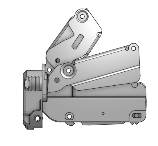
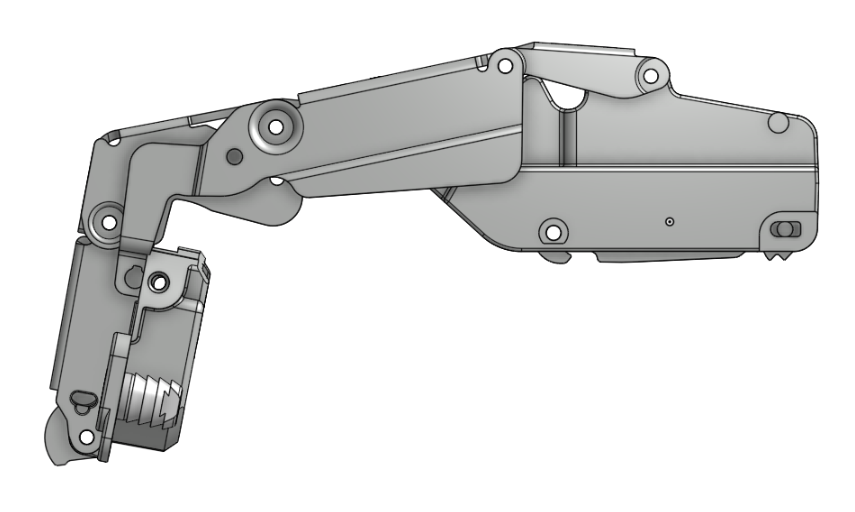
    My issue is not with how to mate the hinge points. I have all of the mate connectors added at each part level, and the function of the hinge works just fine. My issue is that the hinge needs to move from the closed position (the first pic in my first post) to the open position which moves the door 165 degrees (the second pic in my first post). This images shows where all of the mate connectors are at:

    I want to limit the movement to be only 165 degrees, but the mate connectors are all an eight decimal place number, and there is no way that I can find to say I want the hinge cup plate to move from 0 to 165 degrees. In SolidWorks, I could put a hinge limit mate between the face of the cup plate and the front plane and that works just fine. I'm at a loss as to how to do this in OnShape.

  • william_lacey140william_lacey140 Member Posts: 19
    I'm not following what the issue is when you say the holes don't align?
    I didn't explain that correctly. The holes themselves align perfectly. The X and Y axis of the mate connectors do not align since the parts have no geometry that relates to other parts. This creates an odd angle between the axis. In order to get it to work like I wanted, I had to limit one of the revolute mates to be no less than 121.941044 degrees and no more than 264.160396 degrees. There was no way to specify 0 to 165 degrees between any of the mate connectors.
  • william_lacey140william_lacey140 Member Posts: 19
    I would first place explicit mate connectors on the holes in each part I want to use.
    In every part I placed a sketch on the center plane and constrained the sketches to the holes. Then I used those sketches to add explicit mate connectors. I had to do this because if I had used the holes or pins at the reference for the mate connector, I was getting some weird results. The sketches gave me exactly what I was looking for though.

  • NeilCookeNeilCooke Moderator, Onshape Employees Posts: 5,688
    Take a look at doc #15 in the public library - very similar.
    Senior Director, Technical Services, EMEAI
  • martin_kopplowmartin_kopplow Member Posts: 513 PRO
    edited July 7
    @william_lacey140 Ah, now I get it. You've obviously placed all the mate connectors accurately by applying them to the underlaying sketches, for this is a pure 2D mechanism. Now the issue you seem to have is that you want to directly constrain or limit the angle between the two mounting plates: The one that stays in place with the cabinet body, and the one that moves with the door. In SW you could set a hinge constraint between two deliberate entities within the mechanism, where in OS you feel limited to the mates you placed on the axis'. Is that the issue you see?
    1. Depending on how your sketches are built, one method might be to include that into a master sketch via a variable and configure.
    2. You could use the parallel constraint in OS to achieve something very similar to the SW hinge. The parallel has angular limits on the Z-axis.
    Here's a very much simplified exapmle (try to rotate the lower part to see if it does what you need):


  • william_lacey140william_lacey140 Member Posts: 19
    NeilCooke said:
    Take a look at doc #15 in the public library - very similar.
    Neil, can you give me a link to it? I can't seem to find it.
  • william_lacey140william_lacey140 Member Posts: 19
    For more clarification, the total angular travel distance for the cup hinge is 165 degrees. There is no singular point of rotation to define this. I have 7 hinge points and the angular difference between the mate connectors (with the Z axis in the same direction on all of them) from open to close is:
    1. -142.219352
    2. 145.76248
    3. 132.93167
    4. -136.474798
    5. 168.543128
    6. 109.283875
    7. 141.352205
    None of them have a difference of exactly 165 degrees. As a work around, I limited one of the revolute mates to the minimum and maximum angles based on the closed and open conditions, but it doesn't feel like this is an optimal solution. If I'm missing something obvious due to my ignorance of OnShape, please let me know. I've got almost 3 decades of drafting experience using SolidWorks and AutoCAN'T, but I've only used OnShape for about 2 months now. I wouldn't doubt it at all if this was an ID-10-T error on my part.
  • NeilCookeNeilCooke Moderator, Onshape Employees Posts: 5,688
  • martin_kopplowmartin_kopplow Member Posts: 513 PRO
    edited July 7 Answer ✓
    For more clarification, the total angular travel distance for the cup hinge is 165 degrees. There is no singular point of rotation to define this.
    Hi William,
    I guess that is exactly what can be achieved using the parallel mate. In my above sample I applied revolute mates to all the joints, with no limits set, and applied only one single parallel mate to the two mounting plates to control the overall angle of the mechanism and deliberately limited the angle at 25 or something within the parallel mate, just to demo, for I used less joints and won't get your 165° at all. I'm sure this works with your model, too. The parallel mate does not require an explicit point of rotation to be set. Leave all other limits blank, only fill in the max. and min. Z-Angle.


  • joshtargojoshtargo Member Posts: 243 EDU
    NeilCooke said:
    When I go to public documents, they are all just parts made by random people. Are you saying there's a folder of official onshape parts or something?
  • NeilCookeNeilCooke Moderator, Onshape Employees Posts: 5,688
    NeilCooke said:
    When I go to public documents, they are all just parts made by random people. Are you saying there's a folder of official onshape parts or something?
    No - that's just one I did.
    Senior Director, Technical Services, EMEAI
  • william_lacey140william_lacey140 Member Posts: 19
    For more clarification, the total angular travel distance for the cup hinge is 165 degrees. There is no singular point of rotation to define this.
    Hi William,
    I guess that is exactly what can be achieved using the parallel mate.
    I knew it was an ID-10-T error on my part! Or maybe it was a case of cranial rectitus. I didn't even think that the parallel mate could have an angular limit (because it wouldn't be parallel anymore). My problem is solved!
  • nick_papageorge073nick_papageorge073 Member, csevp Posts: 828 PRO
    @martin_kopplow thanks for this parallel mate explanation. I had no idea that was possible. I worked through your example and also applied it to Neil's hinge. It was tricky to get to work on his, but eventually I got the parts moving the correct way. Thanks!
  • eric_pestyeric_pesty Member Posts: 1,887 PRO
    @william_lacey140
    Mates in Onshape takes a bit to get used to. Basically a mate defines degrees of freedom between tow coordinate systems (the tow mate connectors). Any degree of freedom that isn't "locked" by a specific mate type has limits available.

    For example you can use a cylindrical mate and turn it into either a Revolute by adding identical limits on Z or a Slider by adding limits on rotation.

    The parallel mate only locks the rotations along x and y axes so all the other values have limits available. 

    In most cases Onshape only needs one mate between two components but sometimes it helps to have two separate ones and the second one should be chosen to have the fewest locked DoF as possible to avoid over-constraining (hence using parallel mate in this case instead of a "planar")

    Also note that you could consider not adding a limit to the hinge itself and limiting the angle the door itself in a higher level assembly (this does help performance as the software doesn't have to simultaneously solve the limits on the top and bottom hinge of a door.


  • rick_randallrick_randall Member Posts: 330 ✭✭✭
    edited July 8
    Hello, this is how I solved a similar problem. This is a toggle clamp, not a hinge but issues are the same. Look at the mate named "limits". This gives free range of motion (grab handle and move), but limits the total movement (stop to stop). Also, put limits on just one mate only (but I think you already know this).
    eric_pesty might have a point with this, though "Also note that you could consider not adding a limit to the hinge itself and limiting the angle the door itself in a higher level assembly (this does help performance as the software doesn't have to simultaneously solve the limits on the top and bottom hinge of a door."
    Hope this helps.


  • william_lacey140william_lacey140 Member Posts: 19
    @eric_pesty

    That is how I use it in SolidWorks. I leave it as a flexible assembly and use the doors to control the opening and closing of the hinge. This was done more as an example of how to overcome a more complicated hinge mate and learn how OS handles it. If I am going to use this, I would certainly leave the hinge as flexible and control the limits in a higher level/parent assembly.
  • S1monS1mon Member Posts: 2,988 PRO
    Onshape (sub-)assemblies are always "flexible", to use the Solidworks term.
  • eric_pestyeric_pesty Member Posts: 1,887 PRO
    @eric_pesty

    That is how I use it in SolidWorks. I leave it as a flexible assembly and use the doors to control the opening and closing of the hinge. This was done more as an example of how to overcome a more complicated hinge mate and learn how OS handles it. If I am going to use this, I would certainly leave the hinge as flexible and control the limits in a higher level/parent assembly.
    One thing to note: sub-assemblies in Onshape are always "flexible" so there is no such thing as "leaving them flexible".

    One more tip I found useful is to not get to "hung up" on the name of the different mates: think of the names as example of an application that requires these specific degrees of freedom. The "pin slot" is one of the more interesting example as it has applications much beyond a pin sliding in a slot. Here's a discussion on that topic: https://www.youtube.com/watch?v=-BuqWiO_qhE
Sign In or Register to comment.