Welcome to the Onshape forum! Ask questions and join in the discussions about everything Onshape.
First time visiting? Here are some places to start:- Looking for a certain topic? Check out the categories filter or use Search (upper right).
- Need support? Ask a question to our Community Support category.
- Please submit support tickets for bugs but you can request improvements in the Product Feedback category.
- Be respectful, on topic and if you see a problem, Flag it.
If you would like to contact our Community Manager personally, feel free to send a private message or an email.
Noob question about positioning text in an assembly
 bernard_hymmen
Member Posts: 7 ✭
bernard_hymmen
Member Posts: 7 ✭
I have a bit of prior experience with Fusion 360 and am trying out OnShape for the first time. I decided to get started with a simple design for a sign that shows a few street addresses. Creating the basic shapes in a single part studio was straightforward enough, but it's obviously a clunky way to go, especially since the signs are two-sided. That is, the signboard for each address has a front and a back and the address should appear on both sides. I think the right way to do this would be to create a part studio for each address number (i.e. a part studio with just an extruded number like "1234" in it) and then mate one instance of it to the front of the signboards and mate another instance to the back in an assembly.
My struggle is in trying to figure out how to define a mating point for these number parts. The intuitive thing for me would be to define a mating point at the geometric center of the number and then apply a fixed mate between it and a mating point on the geometric center of the sign (same thing for aligning to corners and edges). The problem is that these kinds of ideal mating points often lie in space, off of the number’s physical model. Consider a number like “828”. The corner points of the number’s bounding rectangle all lie on the outside of the curves of the “8”s and the geometric center of the number is just above the “2”’s diagonal (well, depending on font choice), again just off of the physical model.
I’ve been reading about mating points in OnShape and I understand that mating points in space are possible, like the well-known case for holes and circular arcs, but those situations don’t apply here because the curves are noncircular, and the points of interest lie outside them in any case. I also understand that it’s possible to place a mating point at an offset from selected point on the model. Assuming the offset point can be in space, I still don’t know how to get it to a precise point defined by geometry (centers, corners, etc.) rather than a measured distance, which I can’t easily know because of the complex nature of the curves in the font and the character spacing.
Doing what feels essentially like typesetting in OnShape seems like it would be a reasonably common scenario as people must constantly be precisely positioning part numbers, labels, logos, instructional or warning text, and so in their designs all the time. So how is this best done? I feel like I’m either missing some feature detail or am just going about this all wrong.
Here's a link to the document I've been working on:
https://cad.onshape.com/documents/b9c1905278c464b030788e5e/w/f907607ff0ac8779b7a91995/e/f268eb9dd9a768cb7b9fb63b
One side is done in the clunky, all-in-one way and the other is the one where I'm trying to figure out this text positioning stuff.
Best Answer
-
nick_papageorge_dayjob
Member, csevp Posts: 1,094 PRO
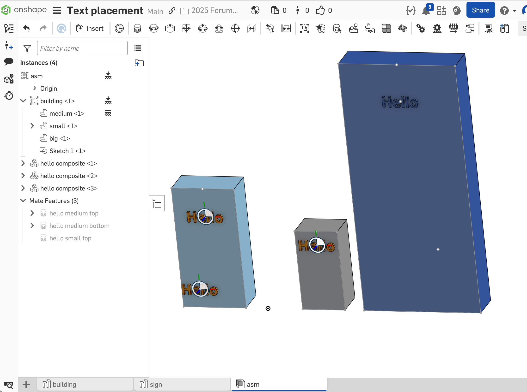
Mate connectors (MC) is a good way to do a general purpose case where you will be reusing the same text in multiple designs. The text has a MC at its center. It can be mated to a MC on a part, or to a point on a sketch (within an assembly). This will make the text a separate part. The left building the text is mated to the 2 sketch points. The sketch has to be inserted into the asm for this to work. The middle building the text is mated to a MC instead. The sketch does not need to be part of the asm in this case, as the MC follows wherever the part goes.
Another approach is to add the text to the root part. This will make them one part. The way to do that is derive the text into the building part studio, and locate it on a MC or sketch point (just like locating it in an asm). Then union it with the part. That is the tall building on the right.
One more caveat, since the text is a bunch of separate letters, I made them all a single composite part.
Take a look and study the various ways:
0
Answers
Hello Bernard. There is, at least one, much easier and clean way to create the signs. Take a look at this document.
The easier way I used was by making use of the Text tool while in the sketch and the use of Configurations (image below). In an assembly you can select any sign configuration to insert.
I suggest creating your sign sketch centered on the origin.
The text tool will show the text along with a center construction line. Place a point on the center of that construction line. Select that point and the origin and use the Intersect constraint to place the text centered to the sign sketch.
Thanks, Scotty, for the explanation and the example document! I hadn’t quite gotten around to working with configurations yet and this example provided a nice intro. I really like the configuration-based approach to the problem I described and the sample document I shared. The thing is, however, that the sample document I was working on is a simplified instance I’m using to build my skills so I can tackle a larger scenario that involves placing standard text across multiple parts and assemblies.
Sticking with the example of a street address, imagine a top-level assembly for an apartment building and its surroundings. In this situation an address might have to go on the side of the building, a unit’s front door, a street sign out front, a parking space, a trash bin, and so on. These placement points would obviously all be on different models and assemblies. I would want to apply a common address, including characters, font, and style (i.e. bold, italics), to all these different parts, each with its own precise positioning (corner of the building, center of the door, etc.). I (now!) see how I could use configurations to control the different sizes that would inevitably be needed for these placements, but I think the positioning is still a challenge.
In the answer’s example, the text is, indeed, well-positioned on the signboard, and I suppose the signboard could be used for precise positioning because it has a simple geometry with easy edges and a center on the part, but I’d like to do this with bare lettering and not have to introduce some artificial backing geometry (like the signboard) just to provide sensible mating points.
I hope that better explains my scenario. Sorry about not being clearer about in before :(
Hey Bernard. Only two points will be needed to place centered text, where you want, on any flat surface. One point is the desired location for the text. That point should be fully defined in that it cannot be moved due to being fixed in one location via dimensions or constraints. The second point is the center of the text. That point is not present upon creation of the text. You will have to place a point at the center of the middle construction line. That being done, select the two points and use a coincident constraint to place the address text at the desired location. I think this is what you're after. - Scotty
Mate connectors (MC) is a good way to do a general purpose case where you will be reusing the same text in multiple designs. The text has a MC at its center. It can be mated to a MC on a part, or to a point on a sketch (within an assembly). This will make the text a separate part. The left building the text is mated to the 2 sketch points. The sketch has to be inserted into the asm for this to work. The middle building the text is mated to a MC instead. The sketch does not need to be part of the asm in this case, as the MC follows wherever the part goes.
Another approach is to add the text to the root part. This will make them one part. The way to do that is derive the text into the building part studio, and locate it on a MC or sketch point (just like locating it in an asm). Then union it with the part. That is the tall building on the right.
One more caveat, since the text is a bunch of separate letters, I made them all a single composite part.
Take a look and study the various ways:
https://cad.onshape.com/documents/688e9f69cb349fb74416b9ab/v/34a7ce0eccebe13370489754/e/107c24f66fcae16b5cf6abd7
Nick, Yes! These approaches seem very natural to me and it's how I was thinking about all of this (well, except for the derived text in the tall building example; that was new to me so, thanks!) when I asked my question in the first place. I just couldn't get it to work :(
It took me a while to figure out that there are some additional caveats to your caveat that eventually got me unblocked. The hierarchy view in your example gave me the big hint: your assembly showed the mating connectors as children of the sign parts, whereas I could only ever get them into my assemblies as siblings in the hierarchy.
Implementing the text as a composite part is the key thing to get this to work. But just creating any ol' composite part isn't quite sufficient. The composite part has to be created as a "Closed" composite. If you don't choose the Closed option, then the individual constituent parts for all the letters stay in the model and, as far I can tell, it's impossible to choose the composite part as the owner entity for the mate connectors. If the parts aren't consumed, then the individual character parts are all you can select as owner entities for the mate connector. Each mate connector can only have one owner part, which means that when you go to insert the whole text part into your assembly only one character will be affected by the mate. When the composite part is the only part available then OnShape will let you select it as the single owner and then all characters will be affected by the mate and behave as one. Yay!
Thanks for putting together the working model to show the details!