Welcome to the Onshape forum! Ask questions and join in the discussions about everything Onshape.
First time visiting? Here are some places to start:- Looking for a certain topic? Check out the categories filter or use Search (upper right).
- Need support? Ask a question to our Community Support category.
- Please submit support tickets for bugs but you can request improvements in the Product Feedback category.
- Be respectful, on topic and if you see a problem, Flag it.
If you would like to contact our Community Manager personally, feel free to send a private message or an email.
Any experience with Neil Cooke's mold design tools?
 dave_franchino
Member Posts: 78 ✭✭
dave_franchino
Member Posts: 78 ✭✭
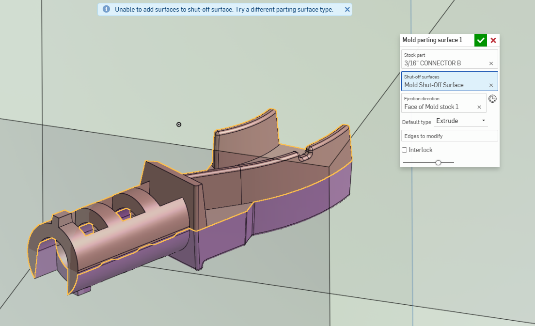
Hey folks, I was wondering if anyone on here had any experience with @NeilCooke 's mold design tools. I watched the webinar but I'm pretty confused on how to establish the parting line surface. I could use a bit of instruction on the meaning of Inner Loops, faces to include and faces to exclude. What is an inner loop? What would cause me to "include" or "exclude" a face and what am I including or excluding them from? Is there any documentation on this that I've not found?
TBH I'm not an experienced mold designer so if these terms are common in the industry I probably need to find a way to educate myself. I've got a part where a series of "holes" are formed by alternating shut offs between cavity and core but I can't figure out how to get this to part out in Onshape using these tools. Any nudges in the right direction would be appreciated.
Answers
I've designed many a mold with this tooling set and find it really useful.
Its's parting-surface creation is useful for general parts, but when you have anything strange going on it's rather crude. So often I would create manual parting faces during the creation of the part even, or in multiple smaller sets of features during mold creation. (grouped in a folder)
E.g. the half cylindrical parting surface would make so much more sense if it's just extended from the inner faces of the part/or extruded, but then in the direction of the cylinder's central axis.
Sometimes it helps for the parting surface creation to choose the direction of the "mold shut off surface" in the opposite direction. play around to find out.
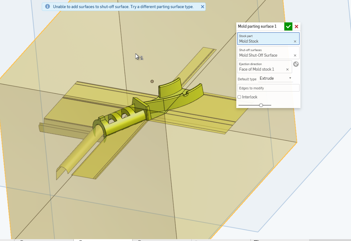
Your part allows for a single flat parting surface most of the way around it seems. The 'mold shut off surface' doesn't do a good job there in creating a single flat face which would be hygienic and less error prone in the future. So I would opt for a more manual approach there.
(there are multiple options for that:
1) create a sketch on the parting surface, intersect the mold faces (or just draw a big circle all around), and create a fill face from there. you can either split face/delete face with the mold shutt off surface, or intersect all those faces as well.
2) select the edges of the parting surface and play around with 'ruled surface' set to 'angle from direction' at 90 degrees and the direction being the ejection direction. this will result in a less clean single surface as well, but you could include the half-cilinder in one go.
for the record:
"Inner loops" are holes in the parting surface, created by holes in the part or undercuts.. These will need to be shut before the mold can be split.
Either by one of the built in methods that you can select for selected loops, or choose "leave open" and model and add those surfaces manually.
(when you choose 'close' Onshape will try to extend the open edges to close the loop, when you choose "fill" it will internally try to create a fill surface to close it.)
"Faces to Exclude" is for faces that are automatically added to the 'mold shut off surface' due to the underlying query, but you'd rather they're not added. (often happens when there's 0 draft or undercuts).
"Faces to Include" is for faces that aren't added to the 'mold shut off surface' due to the underlying query, but you'd rather add them.
All of these are optional settings to allow you to tweak the mold shut off surface to your intention, and perhaps allow easier parting surface creation afterwards.
Good luck with the mold creation!
BTW: If (impact) strength is any factor for your part, you'll need some more fillets especially on the concave corners.
Thanks, that's helpful. To be candid, one of the reasons I wanted to "design" the mold is because I always get a bit confused on where I can add fillets on parts with interlocking shutoffs. I know that I can't have fillets on interior corners where shut off steel is sliding past the other core but I have a hard time visualizing this when I'm designing the part so I thought it would be helpful if I could design a core and cavity and see where fillets don't work.
For example, can I put a fillet in this corner here or does something wonky happen when that insert butts up to the symmetrical insert coming from the other way?
This part doesn't have any impact requirements but I'm just trying to learn a bit more.
I designed the part for 3 degree draft (should be generous, it's just ABS?)
and what I think are obvious shutoffs between the sliding steel that make up the sockets I have at 5 degrees.
I'll read your message more closely and see if i can manually do this. Your description was helpful - thank you!