Welcome to the Onshape forum! Ask questions and join in the discussions about everything Onshape.
First time visiting? Here are some places to start:- Looking for a certain topic? Check out the categories filter or use Search (upper right).
- Need support? Ask a question to our Community Support category.
- Please submit support tickets for bugs but you can request improvements in the Product Feedback category.
- Be respectful, on topic and if you see a problem, Flag it.
If you would like to contact our Community Manager personally, feel free to send a private message or an email.
Engraving on drawing
 Timmy
Member Posts: 11 PRO
Timmy
Member Posts: 11 PRO
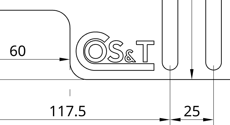
Hi! I currently have a logo (dxf) placed on one of my parts as a 0.1mm cutout. This is looking good on the drawing, but to clarify exactly what needs to be engraved, I'd like to fill this in. This is the logo:
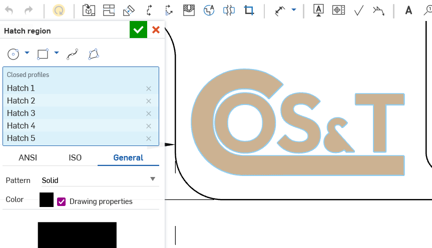
Hatch region seemed like a good idea, but that fills in the ampersand completely:
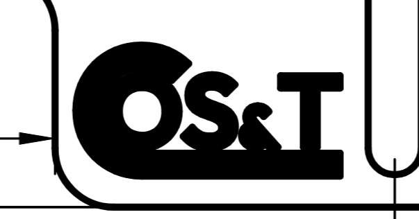
An additional problem is that it is also retaining lines when exporting to PDF, making it look like a chunky mess:
I'm most likely doing this all wrong, so, any suggestions for a better workflow to achieve the goal of a crisp filled engraving would be most appreciated! 🙂
Answers
Have you tried changing the line thickness of your drawing properties?
Also it looks like your part might be really small on your page if the lines are that thick. Perhaps your drawing view is also too small.
RENDERCAD
rendercad.ai - Photorealistic product rendering.
▚▞▚▞▚▞▚▞▚
________________________________________________________________________
You want the whole thing filled in another color, like a pad-print?
You can split the surfaces and make them a separate color, without making a tiny depth cut/extrusion. Then on the 2D, if you make the view "shaded" it will look like it does in the 3d.
They're not, really. The logo is about 44 mm wide, the entire part is 460 x 335 mm. The thickness of the lines looks fine, until it's exported to PDF. I don't really mind the thicker lines, only, for the engraving alone, there should be NO lines. I can see I could change the thickness of the lines, but that would also apply to other lines. Furthermore, I don't see the ability to select and change individual lines.
I'm not sure why the colour would have to be in the drawing. When I do engraving, I usually just make a drawing with thin outlines, then export that (DXF or SVG) to my 2D design or engraving software and fill the faces there. All the graphic design packages can do that with just a mouse click. You could even use freeware like Inkscape to do it, it is quite easy. That way, line thickness is of no relevance at all. If required, the result could be PDFed from there, too.
PDF absolutely refuses to respect line weights. We've run into this many times and it will increase the width of lines significantly (because apparently it "knows best" and helping make things more readable…)
The fill "should" work though… Does the region of the ampersand that gets filled show up correctly in the sketch/ part studio? The may be a small gap in there. Make sure you set the view to "high quality" before you attempt the fill as this might also introduce a gap in the 2D view. This may also be a bug… I've run into issues doing this sort of stuff before.
As for the lines, you could use the "show/hide" lines to hide these (after doing the fill).
If this is just for "illustration", you could create a detail view of the area and use "shaded" display and show the engraved area that way.
I'm positive there are no gaps, as the extrusion works just fine:
But, that did give me an idea. I redrew the inside of the ampersand, and voilà:
Unfortunately, it does look like I'll have to go with manual manipulations (I can do this in Affinity Designer 2) as @martin_kopplow suggested, because now my exported PDF looks like this (filled in entirely!):
I usually use split face for marking engraving on solid parts and then if I want the areas to look different on the PDF, then hatch can be used to change the look of that face on the drawing. If it is a lasercut sheetmetal part I put the engraving in a sketch on the flat pattern and then export the DXF including visible sketches. The visible sketch will be placed in a layer called "MODELSKETCH_VISIBLE" in the DXF and if you open the DXF in notepad (or another txt editor), you can search for the name of the layer and change the color by changing the "7" (code for white) to another number. In my case, I'll change it to 2 because our lasercutters have informed us that their machine automatically detects yellow layers as being designated for engraving instead of cutting. On the PDF, I'll then inform of both the color and layer name as well.