Welcome to the Onshape forum! Ask questions and join in the discussions about everything Onshape.
First time visiting? Here are some places to start:- Looking for a certain topic? Check out the categories filter or use Search (upper right).
- Need support? Ask a question to our Community Support category.
- Please submit support tickets for bugs but you can request improvements in the Product Feedback category.
- Be respectful, on topic and if you see a problem, Flag it.
If you would like to contact our Community Manager personally, feel free to send a private message or an email.
sheet metal bracket with flanges for welding
 WJT
Member Posts: 9 PRO
WJT
Member Posts: 9 PRO
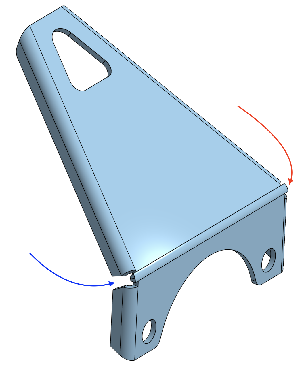
Looking for a little help from the sheet metal experts. I want the flange joints to meet when the bend is made but I can't seem to achieve this effect. The intent is to form the 4 flanges, bend the part, then weld the joint where the flange faces meet (blue arrow). The 'hole" at the corner will remain, so the protruding material (red arrow) needs to go away.
0
Answers
Hard to tell how you made the part of what the various angles are without seeing your document…
But here's one way to do it:
https://cad.onshape.com/documents/211b14084a5b9beda7e98c4d/w/b294400b4ac995dca965e1fa/e/2208eb79dfb436f0424d264f
EDIT: "move face" can do a lot in Onshape so you might just be able to move these bits in…
Also if you bend both flanges 90 you get something like this and reduce the gap with a move face:
I think that first solution is exactly what I need. Appreciate the assistance, Eric.
@Glad to hear it helped!
As a general rule, Onshape sheet metal works really will with a "convert from solid" approach so I would recommend trying to use that workflow whenever possible.
Here's a three part series on modelling the same sheet metal approach in different ways:
"Traditional" sheet metal:
Second part is a variation using the "shaped flange" Featurescript:
Part 3 is using the convert from solid approach but pushed to the extreme (not necessarily best practice but a good case study):