Welcome to the Onshape forum! Ask questions and join in the discussions about everything Onshape.
First time visiting? Here are some places to start:- Looking for a certain topic? Check out the categories filter or use Search (upper right).
- Need support? Ask a question to our Community Support category.
- Please submit support tickets for bugs but you can request improvements in the Product Feedback category.
- Be respectful, on topic and if you see a problem, Flag it.
If you would like to contact our Community Manager personally, feel free to send a private message or an email.
Use face in assembly to slice multiple parts
 nicholas_morris261
Member Posts: 4 ✭
nicholas_morris261
Member Posts: 4 ✭
Hello,
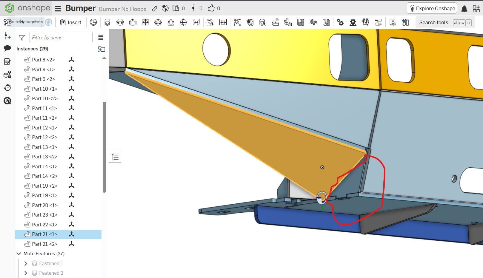
I want to use the face of Part 21 to slice off the corner where parts 1,4, and 20 meet. The parts are not arranged in relative position in my Part Studio, only in the Assembly… help!
0
Answers
The whole point of designing a bunch of parts in a single part studio is to model them in the correct location! So that is the correct way to solve your issue…
You could probably use "in-context" editing but since you put all the parts on top of each other in as single part studio you will have to create a separate context for each of the parts and it's just going to be really messy (wouldn't be as bad with each part in a separate studio).
Hi Nicholas,
Not trying to be a jerk, but, you are using the tool completely wrong. You should have created the "assembly" in a single Part Studio. This would allow you to easily modify parts based on how they fit together.
If you are going to use Onshape on a continuing basis, there is some excellent free training available direct from Onshape.
So, are you defining the sketches from a drawing, or measuring off parts? I don't see how else you could have created this. Your Part Studio should never look like this. The "Part Studio" is really a modeling space where assemblies can and usally should be created. Particularly if the parts are static relative to each other like your bumper.
Thank you for the feedback! Yes, I'm just learning and the biggest challenge is understanding proper workflow! I built my parts from measuring real-life examples. In the part studio I was having issues with my sketches not being fully defined if they did not include a known point (the origin). My solution was to start at the origin for all my sketches, but doing it that way all of my parts overlap in the part studio. What is the proper way to do build fully-defined parts and toe define their positions in Part Studio?
I created two of your parts in the Part Studio, using two different methods.
First method: create a Mate connector at a logical location (where two edged line up for example). Then when you create a sketch, select the Make connector as your sketch plane. Use the Mate connector as your origin to dimension to.
Second method: select geometry from the baseplate to use as your sketch plane. Then either align or dimension from your sketch to geometry on the baseplate to locate the sketch in the final two dimensions.
Use below as a reference:
https://cad.onshape.com/documents/475ca97e22883e396a643c31/w/c817faa4d1dac8ee8e088fea/e/fe41d130d420fe1b93edd951?renderMode=0&uiState=69bf1d772cf966b46f9af0a9