Welcome to the Onshape forum! Ask questions and join in the discussions about everything Onshape.
First time visiting? Here are some places to start:
- Looking for a certain topic? Check out the categories filter or use Search (upper right).
- Need support? Ask a question to our Community Support category.
- Please submit support tickets for bugs but you can request improvements in the Product Feedback category.
- Be respectful, on topic and if you see a problem, Flag it.
If you would like to contact our Community Manager personally, feel free to send a private message or an email.
Custom Feature: Pulleys with custom tooth profiles

Some months back I ran into some challenges with the standard OnShape tooling when it came to modelling a belt and set of pulleys. I took to the forum for help, where I was pointed to a series of custom FeatureScript solutions. Namely:
- This parts studio with a custom belt (though the pitch is wrong). I liked the simplicity of the example, but could not determine how the intricate sketch was made (linked to me by robert_scott_jr_)
- This custom deforming tool (also linked to me by robert_scott_jr_). It had impressive text applications, but seemed too general to apply to my pulley/belt design problem without a more substantial time investment.
- This interesting belt-chain parts studio (linked by elliot_shumsky) , which included code-comment references to sorcery with notes of despair (quite the scroll).
Searches for general solutions yielded:
- This question about creating a belt between existing toothless pulleys. A belt solution was provided there, but didn't address the pulley itself
- A verbatim I-need-to-create-a-pulley forum post. This had a nice gif solution but was for a toothless pulley and modelled the cross section before using a revolve. Something that wasn't exactly the problem I was tacking.
- This post features another tool for creating timing belt pulleys. However, it uses a table of parameters to determine the profile and is fixed to GT2-2M and GT2-3M profiles. It also used an analytical solution for solving points with Sympy which is cool, but seems overkill and dare I say a bit hard to maintain.
Generally, what I found missing from each of these solutions was the ability to create a pulley with a custom tooth profile. However, I was intrigued by the FeatureScript examples I'd been linked. So I went to the learning centre, did the FeatureScript lesson set, and started working on a solution myself.
Pulley Tool ConceptThe concept of the tool is dead simple:
- You sketch a profile of your pulley tooth
- The vertices of that sketch get duplicated a number of times for how many teeth you want along the X-axis
- A pair of 2D coordinate vector transformations are applied to each point, which
- translate that point back to origin
- apply a clockwise 2D rotation to that point about the normal (Z) axis, with the angle proportional to the displacement of that vector on the X-axis relative to origin.
- You apply an extrude to your final sketch to get your toothed pulley
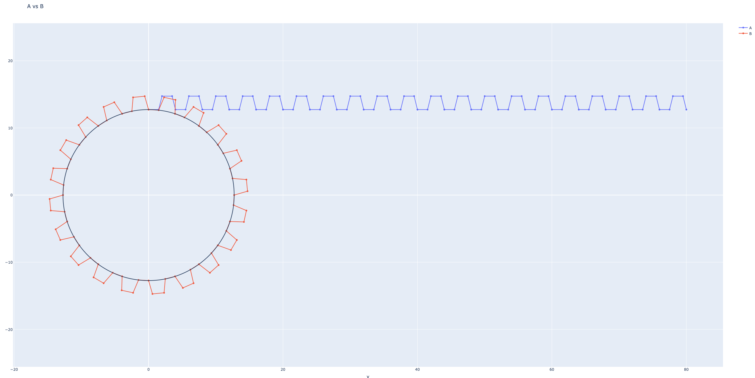
The diagram below that I created with a crude python script illustrates the concept:
 Pulley Tool Feature
The actual feature I've implemented works only slightly different than initially conceived. I'll first link it here, then explain how it works in the following subsections.
- Parts Studio (note I am tinkering in it still): https://cad.onshape.com/documents/867ddfb2e1f7bb5209727a5f/w/907c68d7e58b8e13df5880b7/e/5d59a49dab9637768c28fb3d
- Gist (Github): (note that if you copy-paste this, it relies on an icon import that won't be in your studio so just comment out that line)
Sketch
You start by creating a sketch of your tooth profile. I give an example here of a DIN 7721 tooth profile that I tried to recreate:
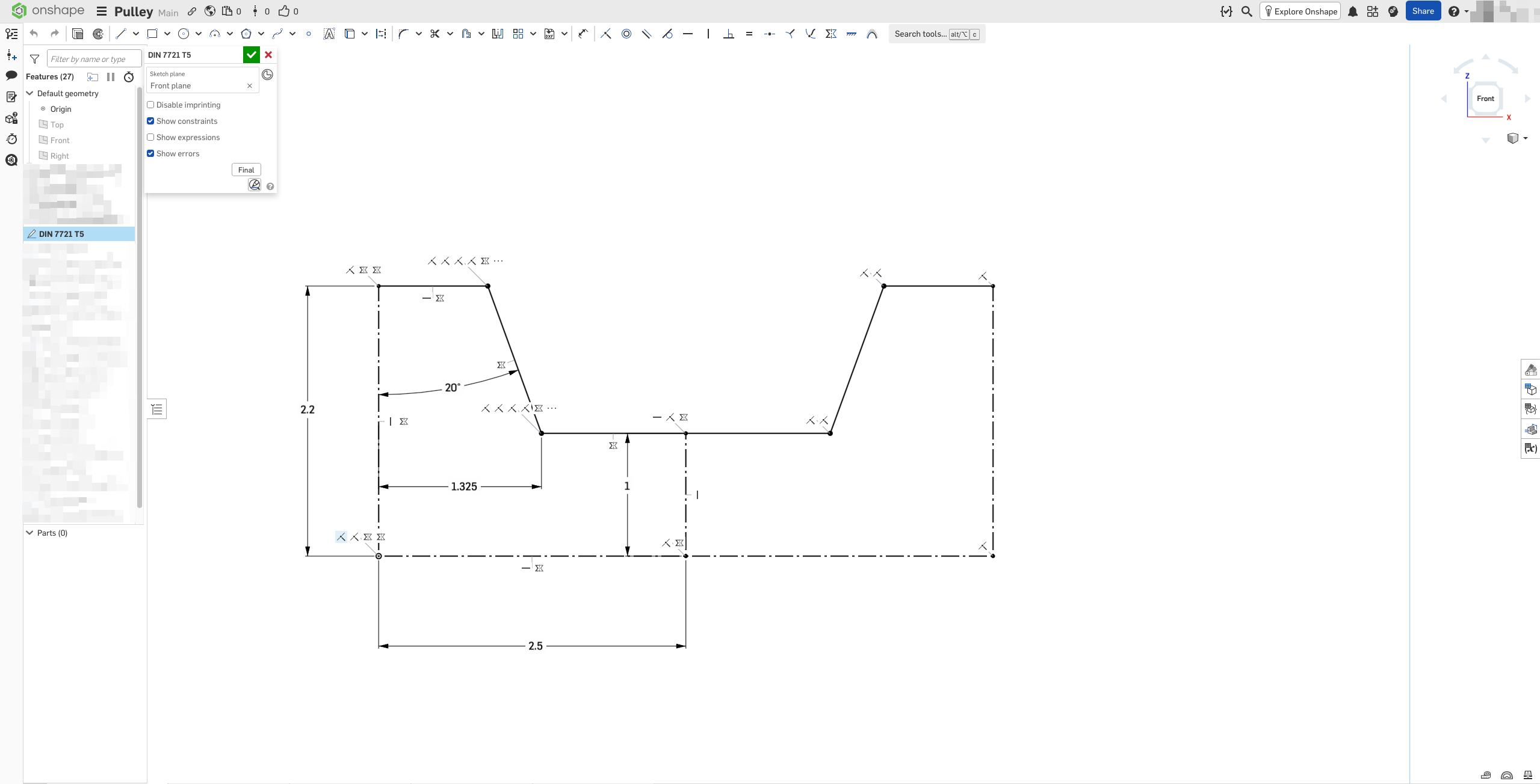
There are a couple of rules about creating a profile that you need to follow:
- Any and all edges that are not part of the top-surface of the profile must be construction-edges (you'll see in the next steps)
- Any edge that faces the surface of the pulley should be non-construction
Select the Pulley feature
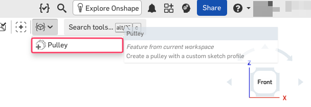
Next, you go to the custom-features menubar icon and select the Pulley feature
Fill in the sketch profile
Here, you've basically got to do three things:
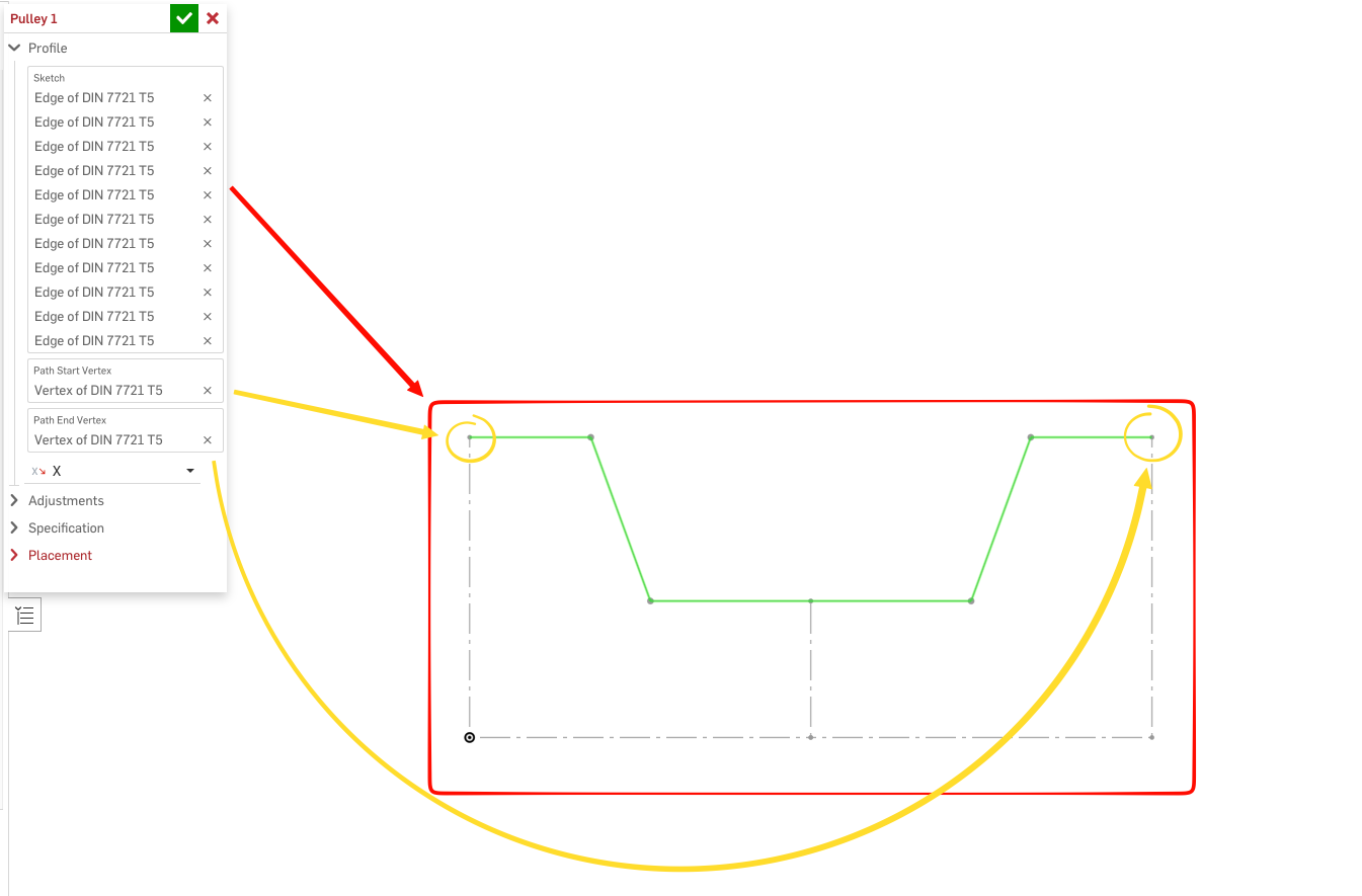
- With the menu context set to "Sketch", click and drag around your entire sketch to select everything in it. This should fill the Sketch box with all selected edges, and you will see a green highlight appear around all non-construction edges. This set of edges is the actual profile of your belt tooth, and the Feature will check that it forms a linear path without branching or loops.
- Select the start vertex and end vertex of the path in turn. They should be the ends of the highlighted green path.
- Finally, select the Axis parallel to that of the profile. This is indicated below with the dropdown box. Since I don't actually know on which face you've drawn this sketch globally, I can't determine it for you (there was an attempt to do so based on the direction of the pitch profile, but that got too complex so this is simpler)
Specify your pulley
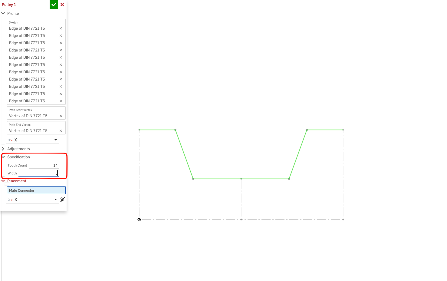
I'll skip the "Adjustments" tab and get back to that later. For now, we simply specify our pulley in terms of teeth and width. Some things to note are:
- The width of the pitch profile is determined from your sketch using a bounding box, and along the direction you specified in the Profile tab.
- The radius of the resulting pulley is determined from the circumference which is in turn determined by the product of the number of teeth you specify and the measured pitch width
Select a Mate Connector
Open the Placement tab and select a mate connector in your Part Studio. Once that is done, you will see your pulley generated on screen. You can reorient the pulley with the provided axis and reverse-direction controls. There's probably a nice way to transform the coordinate system so that the pulley normal aligns with the normal of the mate, but I haven't figured it out yet.
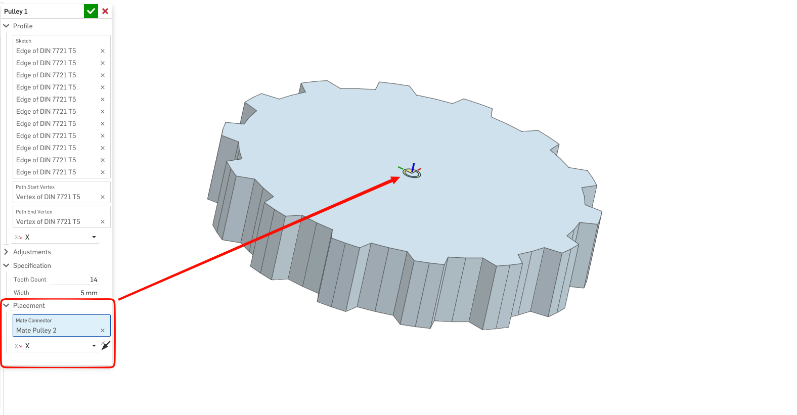
And that's it! It's as shrimple as that.
Apply any adjustments
Now, the adjustments tab offers two functions I developed that are more or less efforts to mitigate unintended side-effects of my approach for creating pulley wheels this way.
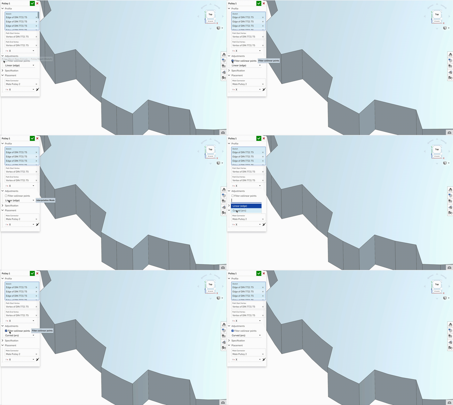
- Filter Collinear Points: Because I used the sketch mirror-tool to duplicate half the pitch profile, I ended up with some extra vertices that don't contribute anything to the overall geometry. When those get transformed in my FeatureScript implementation, they add extra points on the "circle" which just aren't necessary. To get rid of them, I added a collinear points check along the profile edge path which removes such vertices. However, the main use of this function is in service of the next option.
- Linear (Edge) / Curved (Arc): A problem with projecting vertices around a circle and connecting them with edges is that you technically don't get a circle but an n-sided shape instead. To try and improve this, I decided that instead of edges, I could use arcs. The arcs are strung between consecutive edge vertices, and the midpoint is calculated using a linearly interpolated vertex between the two points that also gets transformed. This naturally results in a much "smoother" edge. However, it's not the default because it can result in some rather strange sketch geometry.
Drawbacks of this feature
As you may have gleaned if you read this post this far, the design of this feature has some notable disadvantages:
- Sketches must be simple: Because I'm transforming vertices within edges, any complex geometry in your sketch doesn't get properly transformed. For example, a fancy curvilinear pitch profile with arcs, or the use of a sketch-fillet doesn't work. There are two reasons why I haven't overcome this limitation
- I'm not familiar enough with FeatureScript / queries to properly be able to work with these shapes. I would like to be able to manipulate the vertices of each shape here while maintaining their edges or curve endpoints, but I don't know how to do that.
- I'm also not sure what happens to a sketch fillet that gets transformed. If the fillet is fulfilled with an arc that has a constraint on its angle, then a transformation would violate that constraint. So there's more complexity to think about which I thought I'd leave to later for my first feature.
- Poor performance with high tooth count: Generating a large pulley (1024 teeth) slows down the Feature to a number of seconds before generation of the pulley. The main performance impact comes from the fact that I use a custom 2D path type I defined to help keep track of the pulley profile and ensure I connect the edges properly to form a loop at the end. However, FeatureScript has a limited amount of possible operations on arrays. For example, it does not allow deletion, so some list operations are very inefficient because I must copy and create new lists repeatedly.
- Correctness: I am not a mechanical engineer so I cannot say if this kind of projection is accurate. In fact, I'm willing to wager it isn't.
Benefits of this feature
Though the drawbacks are a definite damper, I can think of a few positives about developing this:
- Simplicity: The concept and code is pretty simple. There's some boilerplate for the 2D path type, but otherwise the core feature (including comments) numbers around 130 lines. Everything is done using provided FeatureScript libraries and functions, so there is no reliance on external calculations or magic tables.
- Flexibility: Because you can define stuff using sketches, a lot more possibilities are opened for tooth profile designs.
Final thoughts / request for help
While I of course hope that some readers here will find the feature useful, I'm more hopeful I can get some assistance in improving this feature by the users of this forum. In the meantime, I'll see if I can 3D-print some of these designs and test them out IRL with some commercially available belts. I'll post my findings here later.
Comments
-
I made my update post with the IRL print tests, but it's not appeared here and hasn't been approved since last Friday. Can moderation check what happened to it? :D
0 -
As promised in my OP, I'm back with an update. Since my last post I've done the following:
- Ordered an off-the-shelf AT5M timing belt
- Used my pulley feature to design a pulley for it
- 3D printed the pulley and tested it with the belt
- Diagnosed and solved issues with my design
Initial Results
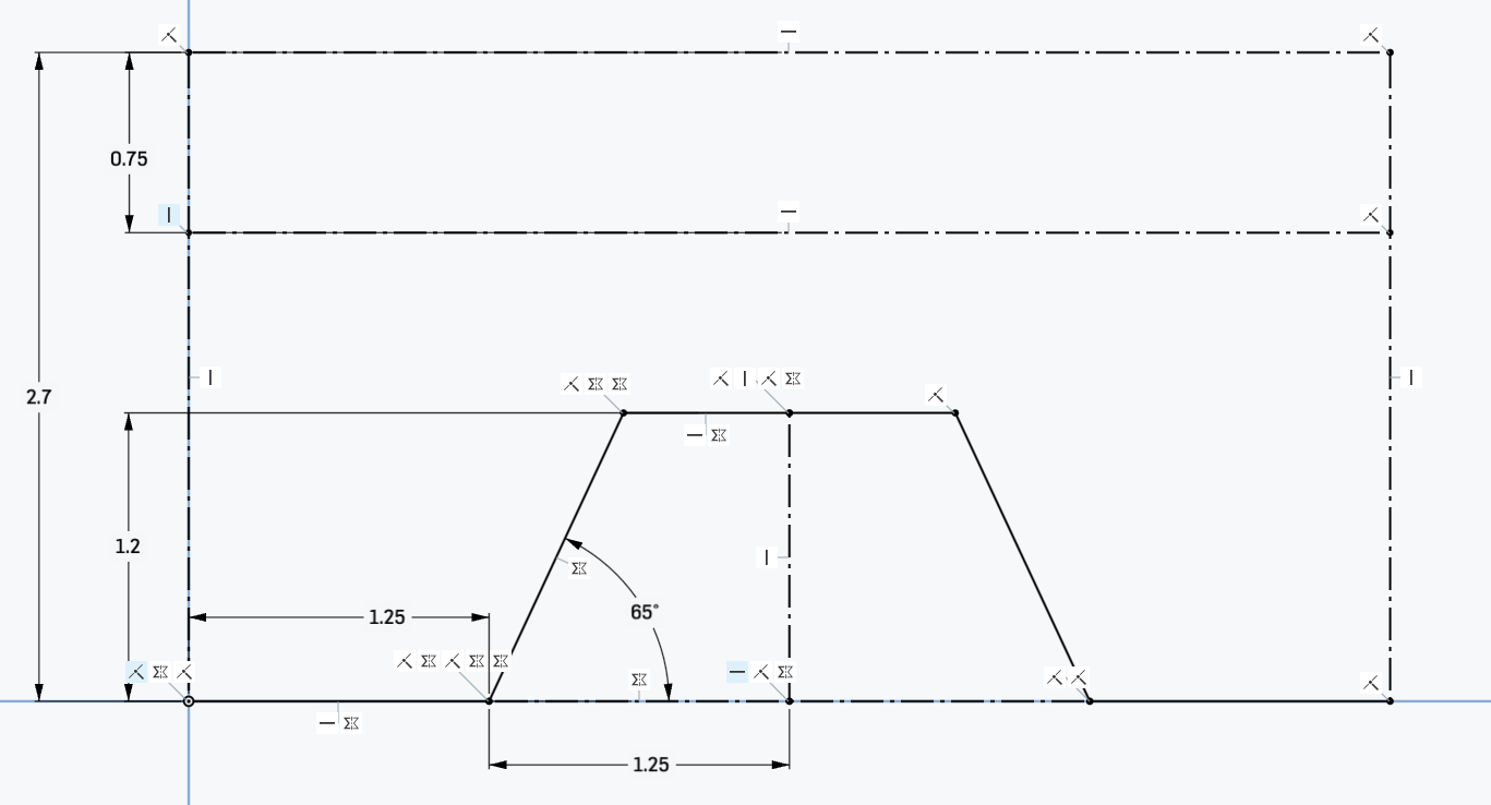
After the belt arrived, I initially printed two pulleys based on a sketch of the AT5M profile
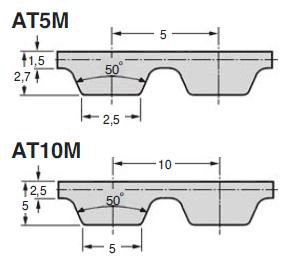
However, I noticed that while any single tooth on the pulley seemed to mesh neatly with the belt, the belt wasn't properly meshing with the pulley as it was wrapped around, with a clear misalignment:
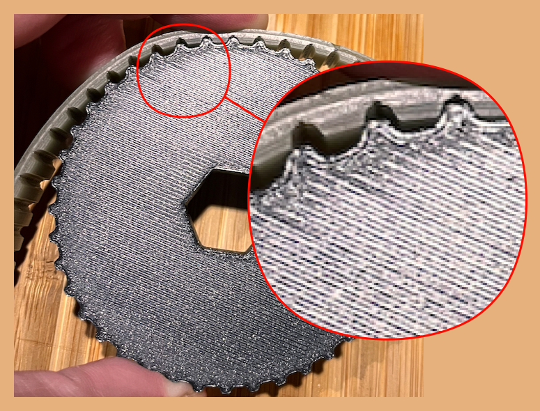
Problem
When I re-examined my feature, I realised that I was calculating the pulley pitch radius correctly, but I was not properly offsetting the sketch geometry when translating. The pulley pitch radius is supposed to be an imaginary line that runs through the solid centre portion of the belt that does not have teeth protruding from it. It serves as a reference for how the belt will wrap around your pulley, and so any geometry must be adjusted with respect to that reference. I was dumbly translating each point with:
point.y += pitchCircleRadiusprior to their rotation transformation, where I should have subtracted the offset of the pitch line too:point.y += (pitchCircleRadius - pitchLineYOffset)In retrospect this was a failure of due diligence, since a trivial search revealed this fact. This post on chiefdelphi by user ClayTownR includes a nice diagram demonstrating this.
Feature Changes
To automatically handle the pitch-line calculation, I updated the FeatureScript attributers to include a new Query for the pitch line.
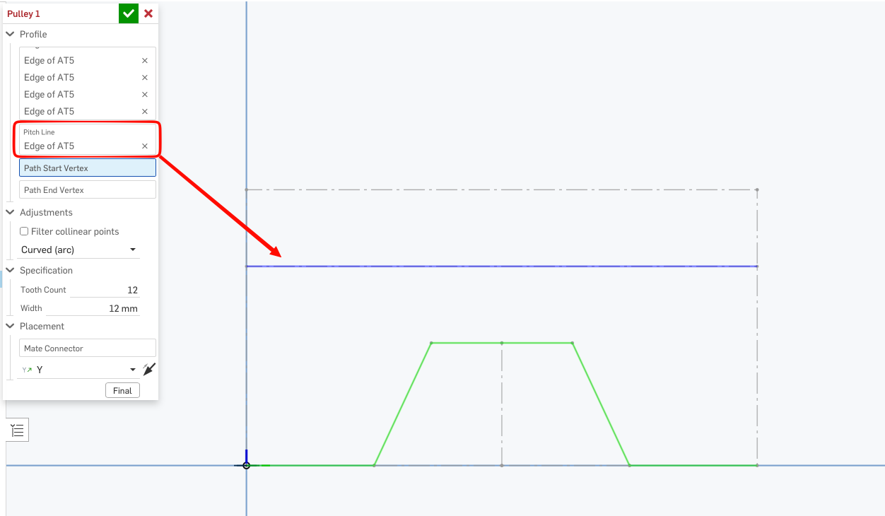
The selected pitch line needs to be a construction line, and additional checks are performed to verify that:
- The pitch-line you selected lies within the sketch plane
- The pitch-line you selected is parallel to one of the axes of the sketch-plane (not the tangent of course)
The nice thing about doing this was that it allowed me to also automatically detect which axis was that for the pitch-width. So I have removed the axis-selection you'll see in the OP. I feel this is a nice trade-off.
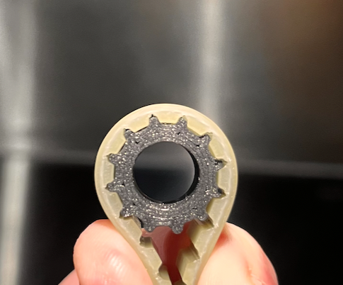
The calculation fix mentioned prior is of course applied, and the result is a pulley that meshes nicely with my belt, at least for this minimum size I printed (the AT5M belt I used recommended a minimum of 12 teeth, which was what I used):
 1
1