Welcome to the Onshape forum! Ask questions and join in the discussions about everything Onshape.
First time visiting? Here are some places to start:- Looking for a certain topic? Check out the categories filter or use Search (upper right).
- Need support? Ask a question to our Community Support category.
- Please submit support tickets for bugs but you can request improvements in the Product Feedback category.
- Be respectful, on topic and if you see a problem, Flag it.
If you would like to contact our Community Manager personally, feel free to send a private message or an email.
Auto Layout Feature
 marena_richardson
Member Posts: 20 EDU
marena_richardson
Member Posts: 20 EDU
I am another member of the team of five college students, mentioned by Jacob Kingery, who got the chance to work with FeatureScript this school year, and this is one of the features we made. Let us know what you think!
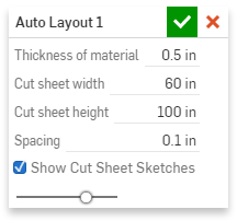
Auto Layout is a Feature we built to lay out parts for laser cutting or other manufacturing processes. Auto Layout finds all parts that match a material thickness inputted by the user and lays them out on cut sheets of a specified width and height with a specified spacing between them using a binary tree bin-packing algorithm right in their original Part Studio. All the input parameters have default values that are set in the config file and that can be modified for maximum ease of use. The algorithm approximates parts as rectangles, and places them in order from largest to smallest onto a cut sheet. Each time a part is placed, the remaining space on the cut sheet is split into a portion above and a portion to the right. The algorithm then tries to place the next part on the top sub-sheet and the right sub-sheet, and the algorithm continues splitting and placing in this manner recursively. With this Feature, anyone can design something fully assembled and easily lay its parts out without needing to create additional Assemblies, Drawings, or Part Studios. Its uses extend beyond laser cutting and one of the clients we worked with used it to lay out desk parts that he was cutting out of a sheet of plywood. The Feature can be viewed here:
The Feature dialog:
An example of Auto Layout being used to lay out desk parts:

Auto Layout Code:
FeatureScript 275;
import(path : "onshape/std/geometry.fs", version : "275.0");
import(path : "b2e35aca6e9ed7a858fa702f", version : "b85c432998567d427f0c5fdb");
annotation { "Feature Type Name": "Auto Layout" }
export const autolayout = defineFeature(function(context is Context, id is Id, definition is map)
    precondition
    {
        annotation { "Name" : "Thickness of material" }
        isLength(definition.thickness, DEFAULT_THICKNESS);

        annotation { "Name" : "Cut sheet width" }
        isLength(definition.width, DEFAULT_SHEET_WIDTH);

        annotation { "Name" : "Cut sheet height" }
        isLength(definition.height, DEFAULT_SHEET_HEIGHT);

        annotation { "Name" : "Spacing" }
        isLength(definition.spacing, DEFAULT_SPACING);

        annotation { "Name" : "Show Cut Sheet Sketches" }
        definition.showSheets is boolean;
    }
    {
        //step 1 - query for all bodies
        //step 2 - find all the planar faces owned by each body
        //step 3 - sort planar faces by size
        //step 4 - use largest planar face to create a bounding box and check
        //         that the depth of the part = the thickness of the material
        //step 6 - If the part has correct thickness, lie flat on the top plane
        //step 7 - space parts out using a binary tree bin packing algorithm
        // Query for all bodies
        var bodies = evaluateQuery(context, qBodyType(qEverything(EntityType.BODY), BodyType.SOLID));
        // Initialize list of parameters necessary for bin packing
        var blocks = [];

        // Initialize list of bodies that are laser cuttable
        var yesParts = [];

        // Iterate through bodies
        for (var i = 0; i < size(bodies); i += 1)
        {
            // Query for planar faces and sort them by their surface area
            var faces = evaluateQuery(context, qGeometry(qOwnedByBody(bodies[i], EntityType.FACE), GeometryType.PLANE));
            var sorted = sort(faces, function(face1, face2) {
                return evArea(context, {"entities": face2}) - evArea(context, {"entities": face1});
            });
            // Check if part has planar faces (is planar)
            if (size(sorted) > 0) {
                var largestFacePlane = evPlane(context, {
                    "face": sorted[0]
                });
                const orientedCSys = planeToCSys(largestFacePlane);
                const boundingBox is Box3d = evBox3d(context, {
                    "topology": bodies[i],
                    "cSys": orientedCSys
                });
                const deltaX = abs(boundingBox.maxCorner[0] - boundingBox.minCorner[0]);
                const deltaY = abs(boundingBox.maxCorner[1] - boundingBox.minCorner[1]);
                const deltaZ = abs(boundingBox.maxCorner[2] - boundingBox.minCorner[2]);
                // Check that the part has a z depth equal to the thickness of the material
                if (tolerantEquals(definition.thickness, deltaZ)) {
                    blocks = append(blocks, new box({'w': deltaX, 'h': deltaY, 'owner': bodies[i], 'rotated': false}));
                    yesParts = append(yesParts, bodies[i]);
                    // Move parts to the top plane and to the origin
                    var transformFromWorld = fromWorld(orientedCSys);
                    var transformToOrigin = transform(-boundingBox.minCorner);
                    opTransform(context, id + ("transform_to_top_and_origin" ~ i), {
                        "bodies": bodies[i],
                        "transform": transformToOrigin * transformFromWorld
                    });
                }
            }
        }

        // Move non laser cuttable parts out of the way
        var noParts = evaluateQuery(context, qSubtraction(qBodyType(qEverything(EntityType.BODY), BodyType.SOLID), qUnion(yesParts)));
        for (var i = 0; i < size(noParts); i += 1) {
            const boundingBox is Box3d = evBox3d(context, {
                "topology": noParts[i]
            });
            var transformToOrigin = transform(-boundingBox.maxCorner);
            var transformAway = transform(vector(-(definition.width * 0.3), 0*meter, 0*meter));
            opTransform(context, id + ("transform_to_origin2" ~ i), {
                "bodies": noParts[i],
                "transform": transformAway * transformToOrigin
            });
        }

        // Everything below this point is for spacing
        var sortedBlocks = sortBlocks(blocks);
        var prevBlocks = [];
        var cutSheetNumber = 0;
        blocks = [];
        while (size(sortedBlocks) > 0) {
            // Run binary tree bin-packing algorithm
            Packer(definition.width, definition.height, definition.spacing, sortedBlocks, cutSheetNumber);
            for (var i = 0; i < size(sortedBlocks); i += 1) {
                var block = sortedBlocks[i];
                // Move parts to the binary tree bin packing location
                if (block[].fit != undefined) {
                    if (block[].rotated == true) {
                        rotateBlock(context, id, i ~ cutSheetNumber, block);
                    }
                    var fitVector = vector(block[].fit[].x, block[].fit[].y, 0*inch);
                    var transformToBin = transform(fitVector);
                    opTransform(context, id + ("transform_to_bin" ~ i ~ cutSheetNumber), {
                        "bodies": block[].owner,
                        "transform": transformToBin
                    });
                } else {
                    blocks = append(blocks, block);
                }
            }
            // Sketch cut sheets if specified
            if (definition.showSheets) {
                var sketch1 = newSketch(context, id + ("sketch" ~ cutSheetNumber), {
                        "sketchPlane" : qCreatedBy(makeId("Top"), EntityType.FACE)
                });
                var newX = cutSheetNumber * definition.width * 1.1;
                skRectangle(sketch1, "rectangle" ~ cutSheetNumber, {
                        "firstCorner" : vector(newX, 0*inch),
                        "secondCorner" : vector(definition.width + newX, definition.height)
                });
                skSolve(sketch1);
            }
            // This condition checks that it is possible to space the parts, prevents infinite loop
            if (size(prevBlocks) != 0 && size(blocks) != 0 && prevBlocks == blocks) {
                println("Cut sheet is smaller than largest part plus twice the spacing");
                throw regenError(ErrorStringEnum.TRANSFORM_FAILED, ["cutSheet"]);
            } else {
                // Here you are left with whatever parts don't fit on the first cut sheet.
                // This loop runs once for each cut sheet.
                prevBlocks = blocks;
                sortedBlocks = sortBlocks(blocks);
                cutSheetNumber += 1;
                blocks = [];
            }
        }
    }, { });

    // Sort parts based on largest dimension
    export function sortBlocks(blocks is array) {
        var sortedBlocks = sort(blocks, function(block1, block2) {
            if (max(block2[].w, block2[].h) != max(block1[].w, block1[].h)) {
                return max(block2[].w, block2[].h) - max(block1[].w, block1[].h);
            } else {
                return min(block2[].w, block2[].h) - min(block1[].w, block1[].h);
            }
        });
        return sortedBlocks;
    }

    // This is a helper function that rotates blocks in place so that they can be
    // placed either vertically or horizontally on the cut sheet.
    export function rotateBlock(context is Context, id is Id, unique is string, block is box) {
        var zaxis is Line = line(vector(0, 0, 0) * inch, vector(0, 0, 1));
        opTransform(context, id + ("rotate" ~ unique), {
               "bodies" : block[].owner,
               "transform" : rotationAround(zaxis, 90 * degree)
        });

        const boundingBox is Box3d = evBox3d(context, {
               "topology" : block[].owner
        });
        var transformToOrigin = transform(-boundingBox.minCorner);

        opTransform(context, id + ("translate" ~ unique), {
               "bodies" : block[].owner,
               "transform" : transformToOrigin
        });
    }

    // Modified binary tree bin packing from: https://github.com/jakesgordon/bin-packing/blob/master/js/packer.js

    // Initializer for the bin packing algorithm
    export function Packer(width is ValueWithUnits, height is ValueWithUnits, spacing is ValueWithUnits, blocks is array, cutSheetNumber) returns array {
        var root = new box({'x': cutSheetNumber * width * 1.1 + spacing, 'y': 0*inch + spacing, 'w': width - 2*spacing, 'h': height - 2*spacing, 'used': false});
        return fit(root, blocks, spacing);
    }

    // Fit function calls findNode to determine recursively where the part fits on the sheet,
    // then calls splitNode to create a bin above and a bin to the right
    export function fit(root is box, blocks is array, spacing is ValueWithUnits) returns array{
        var node;
        var nodeR;
        var block;
        for (var n = 0; n < size(blocks); n += 1) {
            block = blocks[n];
            node = findNode(root, block[].w, block[].h);
            if (node != undefined) {
                block[].fit = splitNode(node, block[].w, block[].h, spacing);
            } else {
                nodeR = findNode(root, block[].h, block[].w);
                // See if a position can be found for the part if it is rotated
                // 90 degrees, if none is found in its original orientation
                if (nodeR != undefined) {
                    block[].fit = splitNode(nodeR, block[].h, block[].w, spacing);
                    block[].rotated = true;
                }
                else {
                    block[].fit = undefined;
                }
            }
        }
        return blocks;
    }

    // Recursively finds a bin where the part will fit
    export function findNode(root is box, w is ValueWithUnits, h is ValueWithUnits) {
        if (root[].used) {
            var right = findNode(root[].right, w, h);
            var above = findNode(root[].above, w, h);
            if (right != undefined) {
                return right;
            } else if (above != undefined) {
                return above;
            }
        } else if ((w < root[].w || tolerantEquals(w, root[].w)) && (h < root[].h || tolerantEquals(h, root[].h))) {
            return root;
        } else {
            return undefined;
        }
    }

    // Once a part is placed, creates a new bin above it and to the right of it
    export function splitNode(node is box, w is ValueWithUnits, h is ValueWithUnits, spacing is ValueWithUnits) returns box {
        node[].used = true;
        node[].above = new box({'x': node[].x, 'y': node[].y + h + spacing, 'w': node[].w, 'h': node[].h - (h + spacing), 'used': false});
        node[].right = new box({'x': node[].x + w + spacing, 'y': node[].y, 'w': node[].w - (w + spacing), 'h': h + spacing, 'used': false});
        return node;
    }
Config file:
FeatureScript 275;
import(path : "onshape/std/geometry.fs", version : "275.0");
// This file contains the defaults for thickness, cut sheet width, cut sheet height, and spacing.
// Edit as necessary.
export const DEFAULT_THICKNESS =
{
    "min"        : -500 * meter,
    "max"        : 500 * meter,
    (meter)      : [1e-5, 0.0127, 500],
    (centimeter) : 1.27,
    (millimeter) : 12.7,
    (inch)       : 0.5,
    (foot)       : 0.04,
    (yard)       : 0.014
} as LengthBoundSpec;
export const DEFAULT_SHEET_WIDTH =
{
    "min"        : -500 * meter,
    "max"        : 500 * meter,
    (meter)      : [1e-5, 1.524, 500],
    (centimeter) : 152.4,
    (millimeter) : 1524,
    (inch)       : 60,
    (foot)       : 5,
    (yard)       : 1.7
} as LengthBoundSpec;
export const DEFAULT_SHEET_HEIGHT =
{
    "min"        : -500 * meter,
    "max"        : 500 * meter,
    (meter)      : [1e-5, 2.54, 500],
    (centimeter) : 254,
    (millimeter) : 2540,
    (inch)       : 100,
    (foot)       : 8.3,
    (yard)       : 2.8
} as LengthBoundSpec;
export const DEFAULT_SPACING =
{
    "min"        : -500 * meter,
    "max"        : 500 * meter,
    (meter)      : [1e-5, 0.00254, 500],
    (centimeter) : 0.254,
    (millimeter) : 2.54,
    (inch)       : 0.1,
    (foot)       : 0.0083,
    (yard)       : 0.0028
} as LengthBoundSpec;
Comments
this is brilliant and works so well. Have looked through so many tools and addons to find a CAD program with a simple feature like this to enable simple laser cutting. My previous tool was clicking on each face, exporting them separately and then lining them up in another programme to get a DXF. This is 100x faster to iterate with. Thanks so much!
Had to do a big assembly with a lot of sheets. It was really a pita generating all the dxf data for laser cutting.
Tested your feature script with this assembly and it worked great...
This will be a great relief in future.
PhD, Mechanical Engineering, Stanford University
https://www.onshape.com/featurescript
https://cad.onshape.com/documents/255176f7aa2bfeb5ae5f7c61/w/4746a25aa7f3639ec6de3894/e/b62215b8f124f54f75c9e4f6
Thanks for making the tool. I hope there is a solution to the problem.
Regards
Brad
It appears that the feature gets unhappy with parts that have flat faces with internal edges. I'm surprised that no one noticed this earlier, but it's any easy fix as it looks like the piece of code that does this doesn't actually do anything besides print out some debugging information. I can post a new document with a fix, but I'd prefer to see if @marena_richardson is still around to make the fix on the original document.
Technical details:
The decomposeBody code at the very end of the feature calls traverseEdgesOfFace, which calls constructPath on qEdgeAdjacent(face, EntityType.EDGE). constructPath will fail if it can't form a continuous path; in this case it fails because a face has more than one loop of edges:
Looks like you're using a fork of the Auto Layout feature, not the original. Your forked version sets a variable with additional info about the paths around parts, but unfortunately that extra logic fails for parts that have holes in them (like yours).
The easiest fix is to remove the forked Auto Layout feature from your toolbar, and instead add the Auto Layout feature from the original document which was linked at the top of this thread:
https://cad.onshape.com/documents/3b3bb87c95d03259328fdb1f/v/adfb24c59b8956528d0e9ac0/e/fcecc760e1bc713ee3aae876
EDIT: After doing that, you can delete and replace the feature in your feature tree
Hope this fix arrives in time for your son's birthday!
Kevin
Thankyou for that tip. It now works much better. I have two thicknesses in my model. 4mm and 1cm. When I select 4mm to be used by the auto layout then all the 4mm items are correctly collected and layout out.
This in itself is not really a problem. I thought I would then try to add another auto layout to collect the 1cm items into another sheet. But this destroys the 4mm layout
Is there a suggested work around for handling multiple cut sheets with different thicknesses?
Conveniently, I just made this improvement on my copy, here: https://cad.onshape.com/documents/576e01dbe4b0cc2e7f46a55d/v/5a1d3dddc86d8e47a1c0d6fc/e/887d6e2324589bfd2058c3e1
Just add multiple auto layout features, and they'll get laid out in separate rows. This version also works with the in-context->copy all in place->further operations workflow demonstrated in this document: https://cad.onshape.com/documents/590a2ea57be40f0ffec8ebee/w/83a9ff55ae7c041eaf0383f9/e/e8ddf59811c55ad691c5362b
@Jake_Rosenfeld
I also reached out to @marena_richardson via forum message to see if we could push my changes to the same document, but haven't heard in a few days, looks like she's likely not monitoring the forum anymore.
PhD, Mechanical Engineering, Stanford University
Her profile says 'Last active May 2016'. We probably won't be hearing back
Yeah, I was hoping for an email notification to get through.
I'll get a standard pdf manual page up and get in touch with Neil to list my copy on community spotlight then so people can reference a document which has the possibility of updates, and if they find bugs I can fix them as I get time.
PhD, Mechanical Engineering, Stanford University
https://cad.onshape.com/help/Content/derived.htm
And then for each thickness create a new part studio.
https://cad.onshape.com/documents/255176f7aa2bfeb5ae5f7c61/w/4746a25aa7f3639ec6de3894/e/397cf25ef20b59d770605577
Not sure if you missed my previous post, but I have a version that eliminates the need for that workaround, here:
https://cad.onshape.com/documents/576e01dbe4b0cc2e7f46a55d/v/d579bce22127d1b439c79cf7/e/b72c231628b5affea0873222
This version updates the FeatureScript to the current version, adds a couple other improvements, and will be updated if and when bugs turn up.
Simply use multiple Auto Layout features, and each will lay out the new thickness parts in a new row, like this:
https://cad.onshape.com/documents/45854f026b387aed9fc9c486/w/5885ce67a07e70b98fe8a202/e/7e24eaab87a08641df65a1df
PhD, Mechanical Engineering, Stanford University
I also came across the auto layout FeatureScript. This is really fancy - thanks @marena_richardson @lemon1324 for sharing this.
Anyway having all the cut-outs in their rectangle boundaries I still need a lot of time exporting each of the dxf faces. I read elsewhere that one can create a drawing of the PS to export all faces at once, but I still wonder whether there is a way to export one cut-out dxf per boundary rectangle.
Any ideas how I can archieve that?
Thanks in advance
Currently the easiest way is to create a sketch on top of the layed-out parts, click the "Use" tool and click each face you need, then export each sketch as DXF.
This method isn't parametric (it won't update if the parts or the layout changes) and it requires some clicking, but I don't think there's a fully automatic workflow that's possible at this time.
The mostly-parametric version I use is to use cropped drawing views for each boundary rectangle, each on its own drawing sheet. You have to manually set these up the first time, but then as long as the number of boundary rectangles required doesn't change, the drawing will update perfectly fine.
PhD, Mechanical Engineering, Stanford University
I like it 👍
thanks for the tips
HWM-Water Ltd
Eduardo Magdalena C2i Change 2 improve ☑ ¿Por qué no organizamos una reunión online?
Partner de PTC - Onshape Averigua a quién conocemos en común
What should I call the repository?
IR for AS/NZS 1100