Welcome to the Onshape forum! Ask questions and join in the discussions about everything Onshape.
First time visiting? Here are some places to start:- Looking for a certain topic? Check out the categories filter or use Search (upper right).
- Need support? Ask a question to our Community Support category.
- Please submit support tickets for bugs but you can request improvements in the Product Feedback category.
- Be respectful, on topic and if you see a problem, Flag it.
If you would like to contact our Community Manager personally, feel free to send a private message or an email.
What are good practices for mating multiple parts in a cut sheet layout?
 adam_geary
Member, csevp Posts: 43 PRO
Again I've tried searching and couldn't find the right combo of terms to find anyone talking about this, so here goes.
I frequently make arrangements of flat parts which fit together in the part studio (cabinets, signs, etc.) and then I need to arrange them in a flat layout for cutting on my 2.5 axis CNC mill. I see the neat Auto Layout tool, but it doesn't nest well, especially with non-rectangular parts.
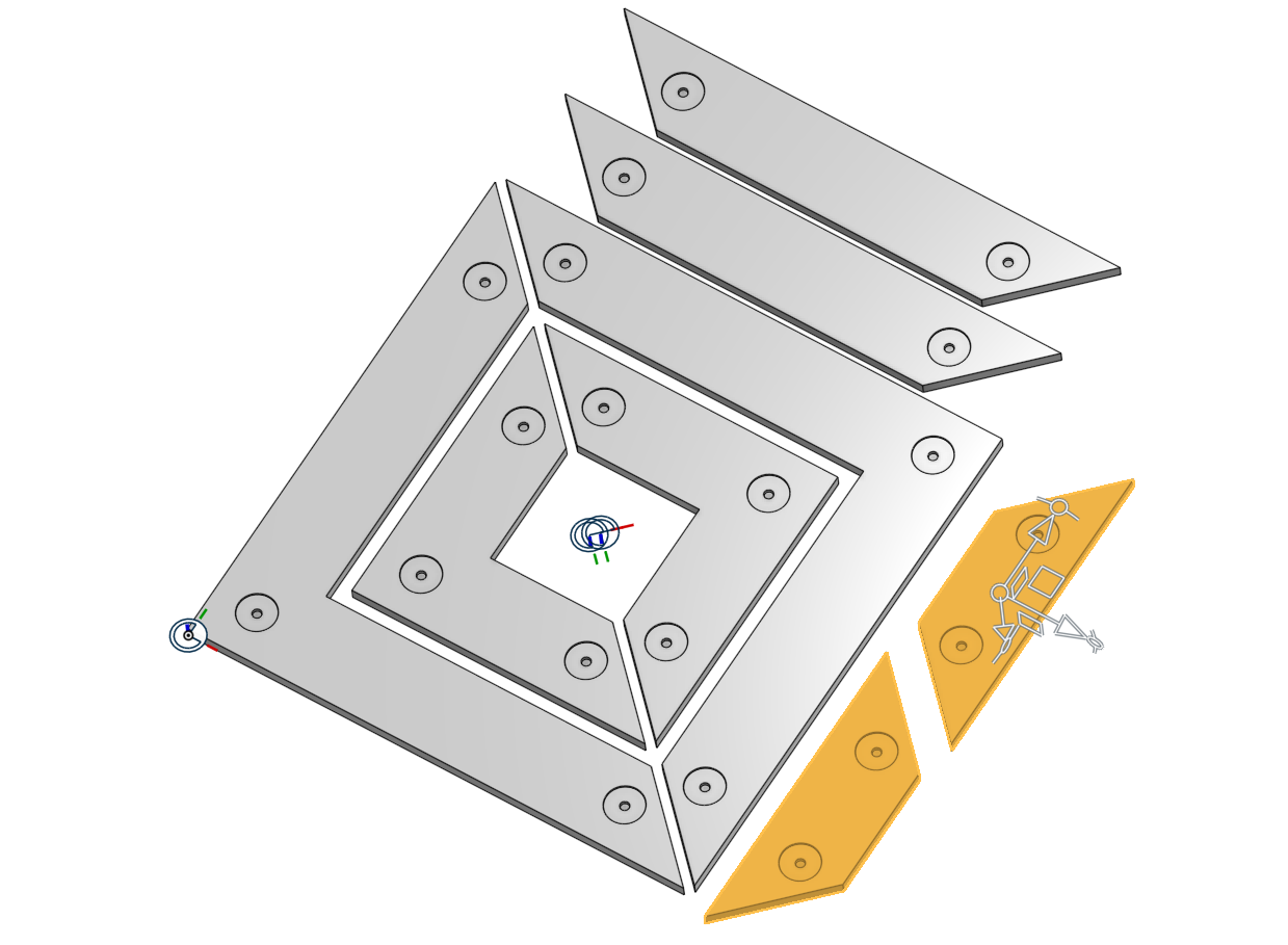
How would you go about mating the parts seen below in an arrangement as pictured with uniform spacing?

In particular, the two highlighted parts are thoroughly baffling me. After much consternation I figured out decent ways to arrange the other parts, but I just can't find a good way to mate those two without making sketches and manually adding mate connectors in the part studio, which is not an acceptable solution for this type of work.
I frequently make arrangements of flat parts which fit together in the part studio (cabinets, signs, etc.) and then I need to arrange them in a flat layout for cutting on my 2.5 axis CNC mill. I see the neat Auto Layout tool, but it doesn't nest well, especially with non-rectangular parts.
How would you go about mating the parts seen below in an arrangement as pictured with uniform spacing?

In particular, the two highlighted parts are thoroughly baffling me. After much consternation I figured out decent ways to arrange the other parts, but I just can't find a good way to mate those two without making sketches and manually adding mate connectors in the part studio, which is not an acceptable solution for this type of work.
Tagged:
0
Answers
1st method:- Use Group to fix selected instances relative to one another. It is very convenient when the instances were all modeled in the same Part Studio in the correct locations relative to one another. Group enables you to keep that relative positioning without having to create Mates.
You can click the entity name in the Feature list, click the entity in the graphics area, or click and drag a selection box around entities in the graphics area.
For both method please refer below video for more detail.
I hope this video will helpful to you.
btw - make sure to let us know if you launch a YouTube channel...