Welcome to the Onshape forum! Ask questions and join in the discussions about everything Onshape.
First time visiting? Here are some places to start:- Looking for a certain topic? Check out the categories filter or use Search (upper right).
- Need support? Ask a question to our Community Support category.
- Please submit support tickets for bugs but you can request improvements in the Product Feedback category.
- Be respectful, on topic and if you see a problem, Flag it.
If you would like to contact our Community Manager personally, feel free to send a private message or an email.
Negative fillet radius?
 michael3424
Member Posts: 754 ✭✭✭✭
I'd like to put an inside (negative?) fillet on a part, much like you'd get with a ball end mill, but can't see a path forward. Is there a way to do that?
My part is a 1/4-in high octagon and I'd like to put a 1/8-in inside radius around the top edge. I can do each edge separately by extruding a circle, but that has to be done on each of the 8 top edges and seems too convoluted. Another work around just occurred to me - use a octagon sketch to put a ledge around the edges and then do a standard fillet at the ledge of the corner. That's still convoluted but much easier.
Anyway, if there's no way to do it with a single tool now, could OnS please add the request to the wish list?
Mike
1
Best Answers
-
 pete_yodis
OS Professional, Mentor Posts: 666 ✭✭✭
I think your request would only be for outside edges, in which case the method recommended by using a swept cut would work just fine... or swept body cut if that's in store. I could see some really strange results in inside corners and inside edges if the fillet tool created "negative" radii. I think it couldn't be applied well to the full scope of cases the fillet tool would be used for.Michael3424 said:Thanks - that worked with a little fiddling around. User error, probably, by not paying attention to what field geometry selections are being placed in.
I still think it would be useful to able to specify a more direct to do this - does negative radius for something like this make sense or would it lead to issues?
Mike
5


Answers
My part is a 1/4-in high octagon and I'd like to put a 1/8-in inside radius around the top edge. I can do each edge separately by extruding a circle, but that has to be done on each of the 8 top edges and seems too convoluted. Another work around just occurred to me - use a octagon sketch to put a ledge around the edges and then do a standard fillet at the ledge of the corner. That's still convoluted but much easier.
Anyway, if there's no way to do it with a singletool now, could OnS please add the request to the wish list?
Mike
- Draw circle on separate sketch
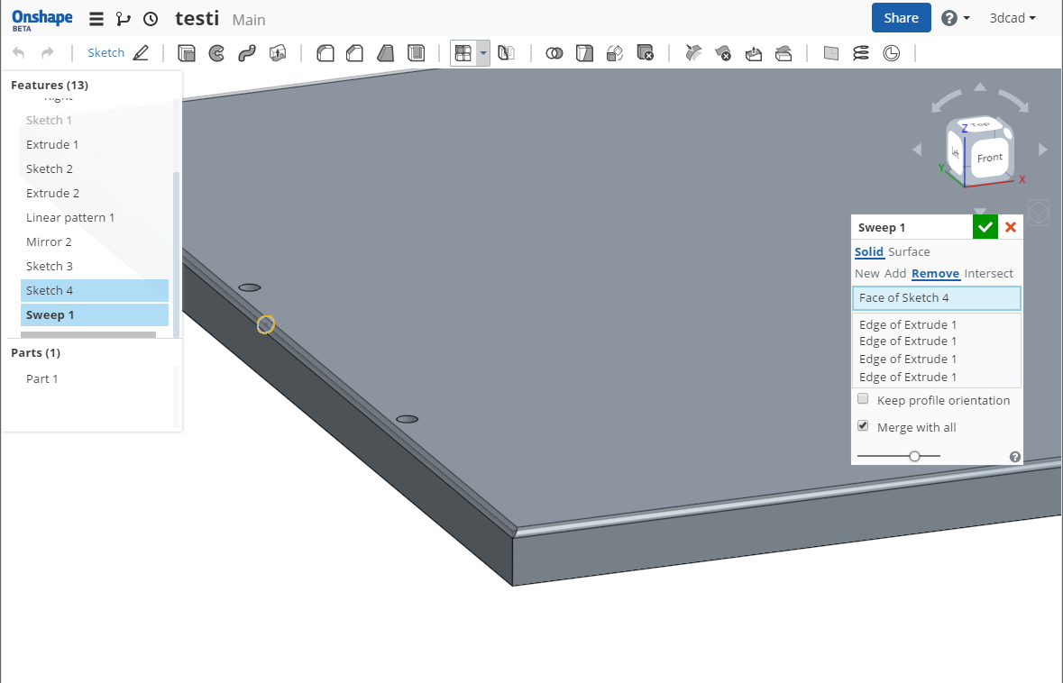
- Sweep that sketch and choose edges of octagon as path.
I still think it would be useful to able to specify a more direct to do this - does negative radius for something like this make sense or would it lead to issues?
Mike
What I would like to see in future after all the basics are there would be sweep tool that acts like 5-ax router and has easy control over depth in different points and angle of the tool. I would like to just draw profile of blade into 'blade library' and then choose blade, add depth/angle points set path with offsets and see the result. Currently even the simpliest paths in 3-ax machine with any varying in depth needs a lot of modeling to follow real world. Usually it's easier to take a piece of mdf and test the looks in real world rather than try it on cad.
Here's example of simple shape that takes less than 3 minutes to program and run with cnc (ball head router) and far longer to model in 3d. If someone want's to give it a try, ballhead R=4mm, depth on both ends = 2mm, depth on intersect = 1mm
Another way to create your rebated octagon would be to provide a plane, set at 22.5 degrees from your construction plane. Extrude the cross section shape you want, complete with rebate, up to that plane. Mirror the resulting wedge. Circular Pattern the resulting wedges and combine into a single solid.
I created a demo model using that method, which anyone can open at
https://cad.onshape.com/documents/5bc9292bc9e9417482eace51/w/6e93f7910b86460499c6a1b8
To my way of thinking, an essential feature of a fillet is edge tangency, which locks down the geometry. Hence the radius alone is sufficient to finalise a fillet. Even the 'sign' does not have to be specified: a "negative" (concave) fillet is automatically applicable to an inside corner, while a "positive" fillet is a convex round to an external corner.
A rebate with a semi-circular profile, which is what you appear to need, is a concave rebate to an external corner. Unlike a fillet, no tangency is inherently specified, so the result is indeterminate.
Given that such a rebate is so different from a fillet, and requires extra information, it seems to me it would be misleading to use the same tool to create it.
Fillets are universal (I can see dozens from where I'm typing this) and intensely functional: they make prismatic shapes durable and safe.
Whereas rebates are a styling feature in most cases, and the profile of the fillet (and the location of the centre of that profile) is whatever the stylist wants it to be.
I was frustrated at spending too much time to find a decent solution, but it appears that as is usually the case in such matters the problem was in the user, not the software. I'm coming here after many years with Alibre/GeoMagic and differences in the UI have me doing some operations with the wrong selections - it's taking a little time to re-orient to OnS's way of thinking.
Andrew - I tried the approach in your example and was able to simplify it a little by playing around a bit.
Mike
Care to share your model? I'm absolutely in favour of simplification
I tried to make a sample file public. If I got that right you should be able to get to it from this link:
https://cad.onshape.com/documents/393a1daa601340eebc193e3d/w/a8ec4819978e4b2085630fc4/e/f63bf800728b4ed8bb8fefa2
Mike
PS - I see the file in my Public folder, so let me know if it isn't there.
Though, I don't like any tools where you can't go back and edit. That's one reason why I'm great fan of Alibre, I can always go back to edit in same dialog which was originally used to create things.
Mike
It took me 10 minutes to create, between opening the browser window and starting to right this comment, the longest part was futzing around with the curve geometry to mimic your picture. It would prob take me 5 more to finish...
Features needed in OS to finish this:
1a. Allow the boolean intersect feature of two surfaces to create a 3D curve, OR
1b. A "project" feature which allows me to project a sketch onto a surface, thus creating a 3D curve, OR
1c. 3D sketching
AND
2. A sweep feature which supports a 3D trajectory.
So close!
Linked[in]
My problems with this approach:
- I wasn't able to create planes normal to tangent of curve endpoint (maybe I'm missing something here?)
- I wasn't able to perform sweep from circle to another (I suppose it's a loft when it goes from figure to another? - which is not supported yet)
so basicly I was stuck in the beginning..
When creating a new plane, select the "Curve Point" option, as this allows you to create a plane through a curve endpoint and normal to the curve itself. I just added one to that public model if you want to check it out...
Linked[in]