Welcome to the Onshape forum! Ask questions and join in the discussions about everything Onshape.
First time visiting? Here are some places to start:- Looking for a certain topic? Check out the categories filter or use Search (upper right).
- Need support? Ask a question to our Community Support category.
- Please submit support tickets for bugs but you can request improvements in the Product Feedback category.
- Be respectful, on topic and if you see a problem, Flag it.
If you would like to contact our Community Manager personally, feel free to send a private message or an email.
How to make this gearing rotate properly
 konstantin_shiriazdanov
Member Posts: 1,221 ✭✭✭✭✭
konstantin_shiriazdanov
Member Posts: 1,221 ✭✭✭✭✭
I created a gearing with intermediate rolling elements, but can't make all the rollers move properly because pin slot mates (that should make rollers move in the slots of separator) starting randomly flip direction by 90 deg, when i'm starting to rotate output shaft
https://cad.onshape.com/documents/5b127d8c24b2f4fe30160ab3/w/a4007bd59e449c044bc650ae/e/d39c27f81560c534939f963f
.
this video shows how it really works, though it is in russian
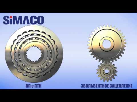 https://www.youtube.com/watch?v=fAamyym1XCk
https://cad.onshape.com/documents/5b127d8c24b2f4fe30160ab3/w/a4007bd59e449c044bc650ae/e/d39c27f81560c534939f963f
.
this video shows how it really works, though it is in russian
https://www.youtube.com/watch?v=fAamyym1XCk1
Comments
It's not perfect, but you may have to look into the profile on the outer ring.
The top roller bearing stays seated while others show gaps.
If you follow my mouse cursor you can see what I mean, it lines up perfect on one side but not the opposite side
https://www.youtube.com/watch?v=FeVg7sP3wVk&feature=youtu.be
Also don't forget the intermediate ball bearing between the cam and the outer roller bearings
But this is over my head
I just buy these gearboxes, not make them
About tangent mates - I just have to use them to make sure all the rollers are in contact with three part at a time