Welcome to the Onshape forum! Ask questions and join in the discussions about everything Onshape.
First time visiting? Here are some places to start:- Looking for a certain topic? Check out the categories filter or use Search (upper right).
- Need support? Ask a question to our Community Support category.
- Please submit support tickets for bugs but you can request improvements in the Product Feedback category.
- Be respectful, on topic and if you see a problem, Flag it.
If you would like to contact our Community Manager personally, feel free to send a private message or an email.
Rotate on Fasten
 shazzner
Member Posts: 3 ✭
shazzner
Member Posts: 3 ✭
So I'm having an issue that I feel has already been solved, but since I'm fairly new to CAD I'm not sure what the terminology would be to search for an answer.
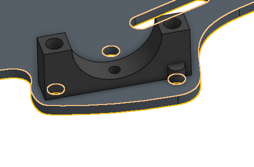
I have a part that I'm trying to fasten to a base. It has two holes and it's at an angle with respect to the x-axis:

(Image two holes on the under side)
So selecting one rim on the bottom of the part:

and fastening to the top of the base rim:

I get it mated easily enough:

Now what I hope would happen is that I fasten the other rim to the top of the base rim and the part will automatically rotate to satisfy both mating restrictions.
However when I do that, I just get it translated over:

Bummer! I was hoping the Solve button would fix the issue but no dice. How do it get the part to properly align up?
I've managed to find a sort of 'cheater' solution in by fastening a screw into the hole, then adding a revolve mate, thus allowing me to manually 'swing' it around. Unfortunately fastening another screw doesn't stop the revolving movement. Not a usable solution.
Also manually rotating each one (of twelve) is no fun, they're all at weird arbitrary angles, and fastening them afterwards seems to mess them up somehow.
Any ideas on what to do? Thanks!
I have a part that I'm trying to fasten to a base. It has two holes and it's at an angle with respect to the x-axis:
(Image two holes on the under side)
So selecting one rim on the bottom of the part:
and fastening to the top of the base rim:
I get it mated easily enough:
Now what I hope would happen is that I fasten the other rim to the top of the base rim and the part will automatically rotate to satisfy both mating restrictions.
However when I do that, I just get it translated over:
Bummer! I was hoping the Solve button would fix the issue but no dice. How do it get the part to properly align up?
I've managed to find a sort of 'cheater' solution in by fastening a screw into the hole, then adding a revolve mate, thus allowing me to manually 'swing' it around. Unfortunately fastening another screw doesn't stop the revolving movement. Not a usable solution.
Also manually rotating each one (of twelve) is no fun, they're all at weird arbitrary angles, and fastening them afterwards seems to mess them up somehow.
Any ideas on what to do? Thanks!
0
Comments
So I add my screws in as I normally would using the standard fasten mate.
Next I
Next I create a Revolute mate from the rim of the hole to the base of the screw.
This allows me to swing it around fence-style.
Now I create another Revolute mate from the second rim to the base of the other screw.
Now when you do that, at first it looks like it failed again and didn't rotate properly. Fear not! Just click the solve button and the lil' bugger will rotate into place.
Thank you konstantin_shiriazdanov for the quick answer!
Worth noting that although the above is a great way there are always others in OS... I like as few mates as possible, especially if I'm reusing parts. As such I might be tempted to apply a mate in the part-studio on the plate. I'd also use the "rotate" option (within the mate function) to align one axis of this mate towards the other hole. Then in the assembly one fixed mate would work as initially intended.
All personal preference.
Cheers, Owen S.
HWM-Water Ltd
Owens is correct.
The best approach would be to add an Explicit Mate Connector to the base part in its Part Studio.
Start a sketch on the face
Draw line between the centers of two of the holes
Close the sketch
Create a Mate Connector at the mid point of the line
In the Mate Connector dialog
1) Make the base the 'owner part'( to make it visible)
2) Select 'move' and rotate the Mate Connector 90 degrees about the x axis (red) to make the Primary Axis (blue) point away from the part.
Now in the assembly create a fasten Mate between this explicit Mate Connector and the implicit one automatically generated at the center of the middle hole in the clamp.
Boom! One Mate!
if this makes no sense, let me know and I will make a sample later today and post the link here.
I hope this helps.
Here is your assembly done with one mate and this IS the best way to do this.
https://cad.onshape.com/documents/57b186fb5574511fb8aad85f/w/087685a35729e6b81eea4d93/e/3fe71ef3931689e88d94bc78
I wonder if it would be possible to have something on a mate connector that we can grab onto and constrain to a sketch entity to set axis orientation. (A bit like the controls on the sketch pattern feature.) That might be more intuitive than poking around in sub menus looking for rotation parameters?
Owen S.
HWM-Water Ltd