Welcome to the Onshape forum! Ask questions and join in the discussions about everything Onshape.
First time visiting? Here are some places to start:- Looking for a certain topic? Check out the categories filter or use Search (upper right).
- Need support? Ask a question to our Community Support category.
- Please submit support tickets for bugs but you can request improvements in the Product Feedback category.
- Be respectful, on topic and if you see a problem, Flag it.
If you would like to contact our Community Manager personally, feel free to send a private message or an email.
Naughty Loft
 michał_1
Member, Developers Posts: 215 ✭✭✭
Hi everyone, I do have a problem with a loft command. I do design a handle (for a toolbox or similar type of case), to define its shape I use mainly conic arcs. The shape is trivial and didn't expect to have any problems, but unfortunately, I do have. Here's the case:

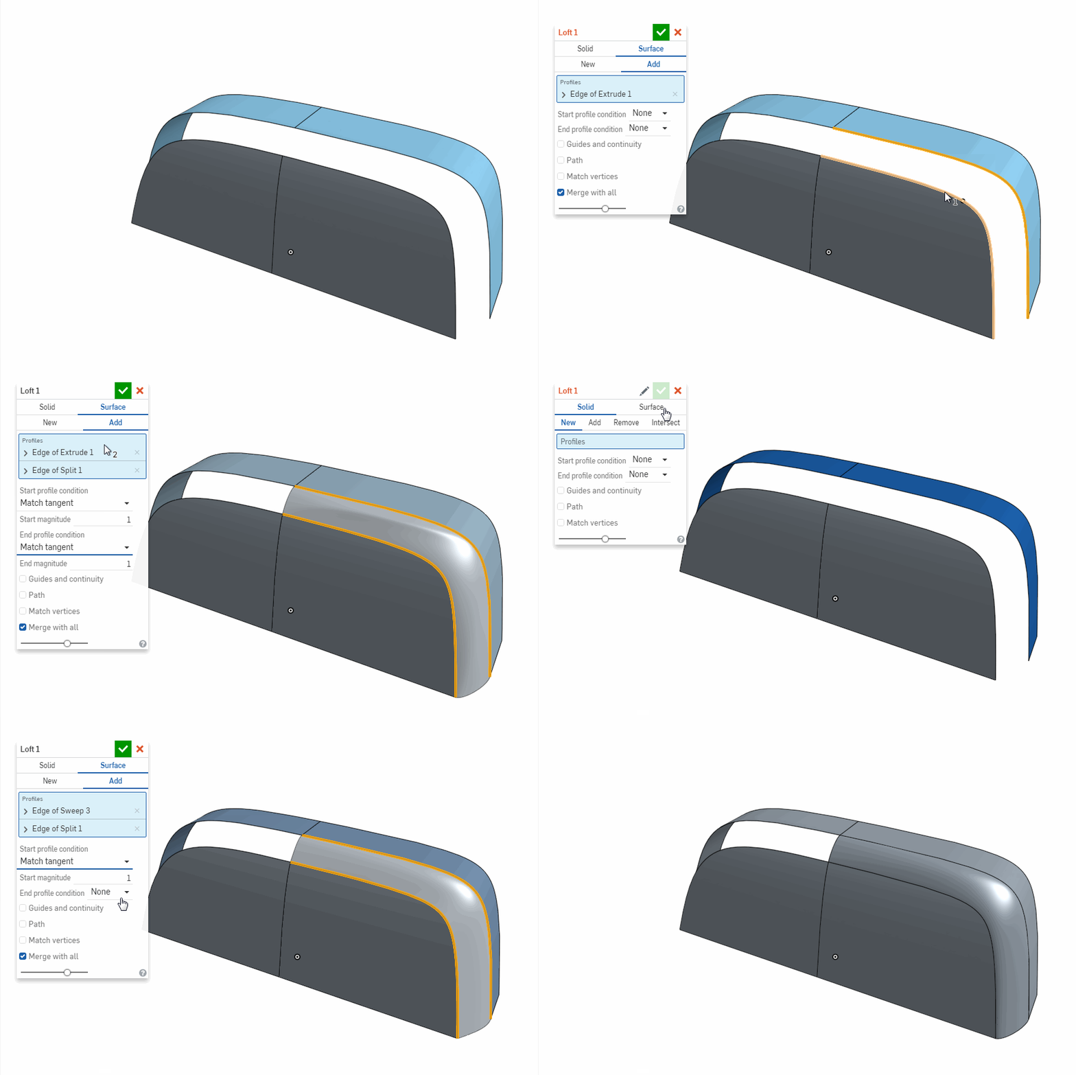
The first model (light blue) is the original approach, and you can see an awful fold/crease on a lofted surface. I was guessing that it could be because of conic arcs (it looks for me that extrusion of a conic arc doesn't build NURBS surface, but rather some kind of parametric surface), so with the second approach (darker blue) I've used spline, and while it looks a lot better it has the very same problem. Below you will see another gif, I've added one more example where I use conic arcs but instead of an Extrude, I use Loft, to get NURBS from conic arcs. Eventually, I do also use MoI blend tool to show how this transition should look like:

I know I could report this as a bug, but I think that the loft algorithm is built as it is purposely, and it fails in this example, not because of a bug, but rather because of some principle rules. Secondly, I also expect that conic arcs (parametric surfaces form conic arcs?) have an impact in creating that fold/crease.
What I would like to hear from devs is an insight, I don't expect for this to be resolved immediately.
What these gifs are missing are the guide curves which I've used eventually. They did improve how the shape looks, but since I built a crease edge on it, any distortion is "enhanced" and not acceptable for aesthetic reasons.
I've come across those problem a few times more in the past. They were less obvious, and I didn't have time to test them, but I will try to replicate them when I will have some time.
I think this is a serious concern. I understand that Loft is a solid modeling tool, and we expand its use beyond for what it was meant to be used, but we need a better Loft for surfacing or a new tool (here's my another guess/impression, I have a filling that we actually have two algorithms in Loft, one simply adjust the first row of CVs, each side, using CVs count of picked curves/edges. The second algorithm approximate initial curve network and create much denser CVs layout but also more even spaced layout).
Here's the document:
https://cad.onshape.com/documents/2b8c4fe532fd13f7917e8dac/w/ba9a953af1af34d39455767e/e/1de06c3ae1fd3cf046f3037b

The first model (light blue) is the original approach, and you can see an awful fold/crease on a lofted surface. I was guessing that it could be because of conic arcs (it looks for me that extrusion of a conic arc doesn't build NURBS surface, but rather some kind of parametric surface), so with the second approach (darker blue) I've used spline, and while it looks a lot better it has the very same problem. Below you will see another gif, I've added one more example where I use conic arcs but instead of an Extrude, I use Loft, to get NURBS from conic arcs. Eventually, I do also use MoI blend tool to show how this transition should look like:

I know I could report this as a bug, but I think that the loft algorithm is built as it is purposely, and it fails in this example, not because of a bug, but rather because of some principle rules. Secondly, I also expect that conic arcs (parametric surfaces form conic arcs?) have an impact in creating that fold/crease.
What I would like to hear from devs is an insight, I don't expect for this to be resolved immediately.
What these gifs are missing are the guide curves which I've used eventually. They did improve how the shape looks, but since I built a crease edge on it, any distortion is "enhanced" and not acceptable for aesthetic reasons.
I've come across those problem a few times more in the past. They were less obvious, and I didn't have time to test them, but I will try to replicate them when I will have some time.
I think this is a serious concern. I understand that Loft is a solid modeling tool, and we expand its use beyond for what it was meant to be used, but we need a better Loft for surfacing or a new tool (here's my another guess/impression, I have a filling that we actually have two algorithms in Loft, one simply adjust the first row of CVs, each side, using CVs count of picked curves/edges. The second algorithm approximate initial curve network and create much denser CVs layout but also more even spaced layout).
Here's the document:
https://cad.onshape.com/documents/2b8c4fe532fd13f7917e8dac/w/ba9a953af1af34d39455767e/e/1de06c3ae1fd3cf046f3037b
0
Comments
projektowanieproduktow.wordpress.com
i was able to get rid of the crease by creating to splines (highlighted above) and lofting between them using the edges of the handle surfaces as guides instead of lofting between the handle edges as you have done above. you can play with the splines to get better curvature if you like. The lofting function is very powerful but you have to define the shape properly. otherwise if you make it guess it will usually produce an ugly crease.
https://cad.onshape.com/documents/ad2b5493902a6ce389c8d6a8/w/6448fb10de04831f0a26880f/e/6bb3145bfcbcb34a8edf008b
The image below was the result of the fill surface command.
https://cad.onshape.com/documents/5a56c9f3d2d7b1a4a495543b/w/3273fbf7750441a7a7f60c39/e/bbc548b64c5c1899f68ddd4f
projektowanieproduktow.wordpress.com
projektowanieproduktow.wordpress.com
I've created my original document 12 days ago and immediately I run into that fold. For the next few days I was trying every iteration I could think off, that would improve that faulty surface, but would not change the way model was planned to be articulated (by articulation I mean the shape and topology).
I was adding guides (sketches, curves, edges...all) in numerous scenarios, at the ends, with additional near the "bends". I was trying different directions of loft, also where guides became profiles. Since that handle is meant to be symmetrical I was lofting from a sketch on a symmetry plane (with normal to profile), from an edge of extrusion (like on images from my first post), but also through the symmetry plane (that one looked extraordinary). I was also trying splines instead of conic arcs.
All that in different configurations.
These were dozens of iterations until I went to a conclusion that without varying an articulation I'm not gonna succeed. This is my plan, to eventually model similar a handle but with different topology. I don't consider workarounds or almost good model since the only purpose this model will serve is to be an illustration for lecture (article) about designing ergonomic handles (https://projektowanieproduktow.wordpress.com/2017/10/20/plastic-part-design-ergonomia-uchwytu-cz-2/).
At this point, I've decided to report that behavior before I will proceed with my work on that model.
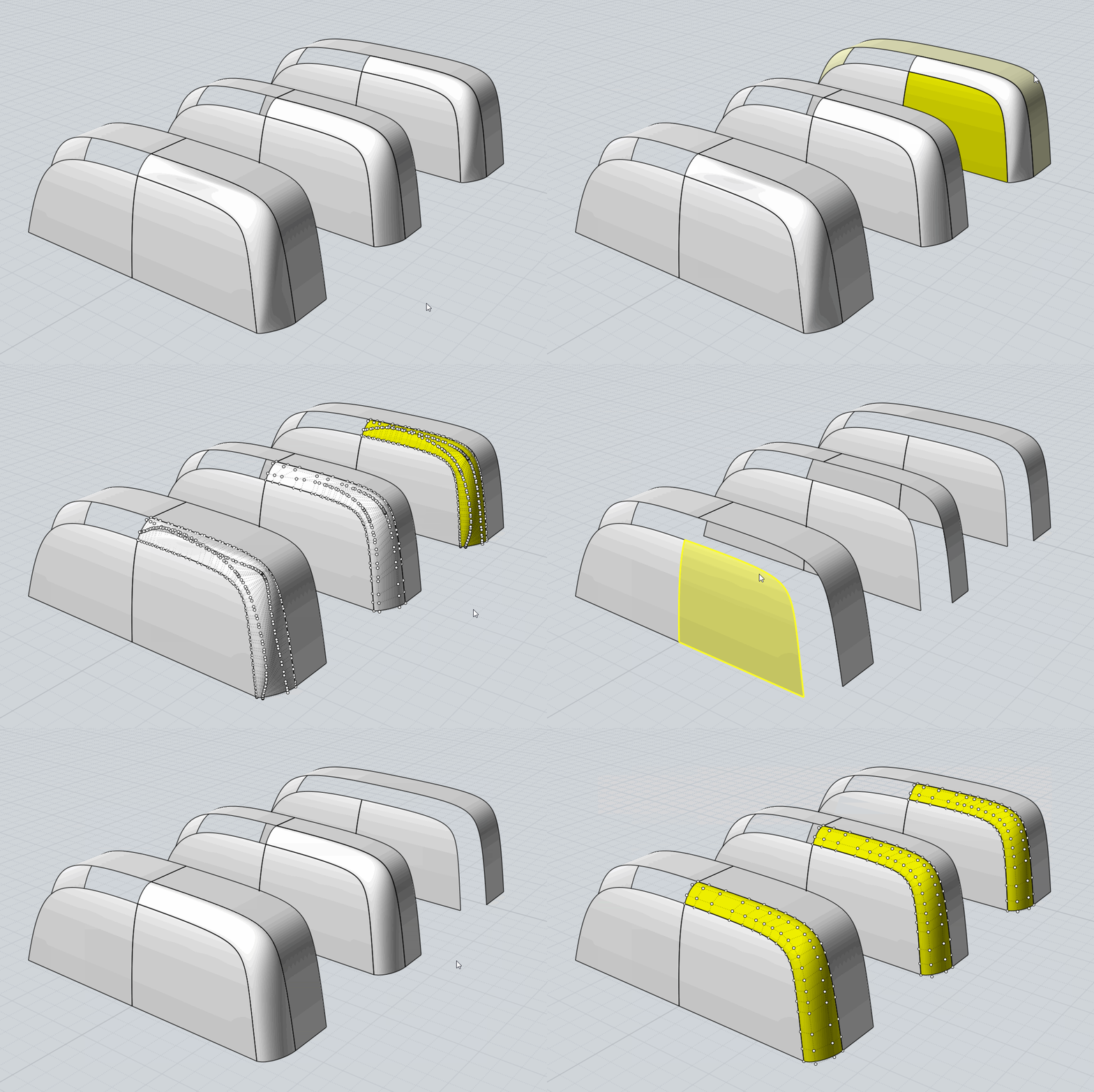
Split3 was an indication that something is wrong, so I've open that model in MoI which can expose underlying CVs layout. I've taken new pictures from MoI, this time those are 3 Onshape lofts (with different magnitude) and 3 MoI blends (also with different magnitude):
Neil, can you tell me what justifies this CVs taking this weird wavey shape, what pieces of original geometry contain such data? Why an increase in magnitude doesn't result in a linear change in CVs layout (like in MoI) but rather have some weird acceleration? How that is caused by consistent data of conic arcs???
projektowanieproduktow.wordpress.com
Thank you for your investigation. We'll have to take a close look into the reasons for such behavior.
projektowanieproduktow.wordpress.com
Thank you for that experiment.
Before that, I also want to show how the discussed part looks with guides:
slightly better.
Same set but, the loft is created from a guide to guide, where old profiles are now an actual guides:
still too dense at the corner, so trim is a wave:
What if we could have a tool like "surface from curve network", it would look like that:
and trim:
this one look much better.
I suspect that Loft tool is actually using two different algorithms. One is "dump" matches and places CVs accordingly to count and placement of curve CVs. The second one is applied when count and position don't match. Now loft is approximating a new number of CV's, and instead of aligning first rows of CVs, place them based on calculated values. Here is a file created to illustrate this distinction:
https://cad.onshape.com/documents/05250b53ae8505aa1fb7b522/w/1135e7d482bb04133663b521/e/91b92fe3add69d0aae136f19
Now let see what this file contains.
The first loft is a loft from one curve to another with just two guides:
The second one is almost the same, the only change is that I have one more guide, in the middle:
as we can see in one direction CVs layout is approximated. After adding a profile in the middle surface is approximated in both directions:
Now look how Network tool in MoI works:
Regardless of how many curves are used I get surface based on approximated data with evenly laid CVs. It's very similar to the loft when it's forced to do an approximation. What is missing is a factor that would make CVs layout more even:
Since used curves are planar, the correct layout is rectangular, if viewed from the top.
That my idea in a sketch. I still would like to see an improved loft, but new network tool might be useful.
projektowanieproduktow.wordpress.com
projektowanieproduktow.wordpress.com