Welcome to the Onshape forum! Ask questions and join in the discussions about everything Onshape.
First time visiting? Here are some places to start:- Looking for a certain topic? Check out the categories filter or use Search (upper right).
- Need support? Ask a question to our Community Support category.
- Please submit support tickets for bugs but you can request improvements in the Product Feedback category.
- Be respectful, on topic and if you see a problem, Flag it.
If you would like to contact our Community Manager personally, feel free to send a private message or an email.
Laying out parts or sub-assemblies to determine specific spacing
 ts_sklett
Member Posts: 9 ✭
This is more of a technique or "best practice" question than a specific feature question.
I've been thinking for a few days how to even ask this question and have finally settled on using a fictitious scenario to simplify things.
If your eyes glaze over reading the following question, you may want to check out the public sample document and screen shot at the bottom.
I am building a custom machine that will apply a label and heat shrink the label on a large cable every 12 inches. Each of the two steps are distinct operations that are performed as the cable proceeds through the machine.
Example scenario:
In OnShape I have the following parts/assemblies (so far):
If you stuck with me this far, THANK YOU! I'm really looking forward to what some of you have to say. If my example and explanation don't cut it, if you don't understand what I'm trying to do, please check out the following example document:
https://cad.onshape.com/documents/3359a7d2ce8c9b7dc76a08d2/w/41a017d624d8284e3ebb5725/e/a9b07273fe2bce62bfdb3f00
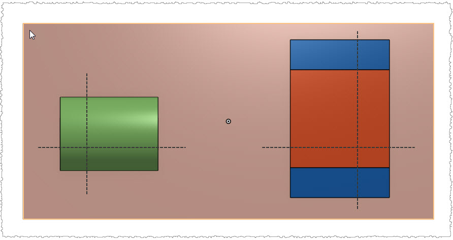
Imagine that the center lines illustrated in this screen shot are what I want to use to position my parts and assemblies:

I've been thinking for a few days how to even ask this question and have finally settled on using a fictitious scenario to simplify things.
If your eyes glaze over reading the following question, you may want to check out the public sample document and screen shot at the bottom.
I am building a custom machine that will apply a label and heat shrink the label on a large cable every 12 inches. Each of the two steps are distinct operations that are performed as the cable proceeds through the machine.
Example scenario:
- Cable is loaded into the machine to the point the feed rollers grab it
- When the machine runs the feed rollers pull the cable through a set distance (steps) and stop
- The machine first stage applies the label while simultaneously 12" further down the heat shrink operation is running
- The machine feeds 12" of material and repeats the application/shrink operations
In OnShape I have the following parts/assemblies (so far):
- Various Part Studios for machine parts like frame, control cabinet, etc.
- Assemblies for the label application operation and the heat shrink operation
- Assembly for the entire machine
- The sub-assemblies don't have an obvious edge or reference to use for a mating connector. I suppose I could try to pick something that is "close" to the center-line of the operation, but it wouldn't be accurate. I found myself wishing I could have a construction line on my sub-assemblies that represents the center-line of the operation (that I would use to space them apart by 12")
- Although I plan to have the application and heat shrink sub assemblies mounted to a common steel plate, I don't yet have any holes defined because, well I don't know where to put the holes (see #1). If I had holes I could use Mate connectors to position things.
If you stuck with me this far, THANK YOU! I'm really looking forward to what some of you have to say. If my example and explanation don't cut it, if you don't understand what I'm trying to do, please check out the following example document:
https://cad.onshape.com/documents/3359a7d2ce8c9b7dc76a08d2/w/41a017d624d8284e3ebb5725/e/a9b07273fe2bce62bfdb3f00
Imagine that the center lines illustrated in this screen shot are what I want to use to position my parts and assemblies:

Tagged:
0
Answers
https://cad.onshape.com/documents/b25bba31294e9a24aee98d2d/w/1bee3a27987e41f7ca647138/e/01f3fd9480fc8e9251d118d5