Welcome to the Onshape forum! Ask questions and join in the discussions about everything Onshape.
First time visiting? Here are some places to start:- Looking for a certain topic? Check out the categories filter or use Search (upper right).
- Need support? Ask a question to our Community Support category.
- Please submit support tickets for bugs but you can request improvements in the Product Feedback category.
- Be respectful, on topic and if you see a problem, Flag it.
If you would like to contact our Community Manager personally, feel free to send a private message or an email.
How do I correct holes that are on the wrong axis?
 CAD_SSP
Member Posts: 45 ✭✭
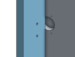
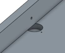
Thanks to some previous help here, I have managed to cut some holes using the hole tool but depending on the orientation of the part the holes end up incorrectly positioned.
Not actually an issue currently as I will always work in one plane but I would love to make the feature universal for future proofing.
Correct holes:

Incorrect Holes:

The FS is here
Please excuse the somewhat messy and clumsy code I haven't had a chance to streamline it yet!
Not actually an issue currently as I will always work in one plane but I would love to make the feature universal for future proofing.
Correct holes:

Incorrect Holes:

The FS is here
Please excuse the somewhat messy and clumsy code I haven't had a chance to streamline it yet!
Tagged:
0
Answers
I don't think I'll be able to debug this for you without spending a bunch of time on it, but I do have some tools that can help. If you press the button at the top of your part studio that looks like '{✔}' it will open the FeatureScript console at the bottom of the document. Then, if you put a 'println(...)' or 'debug(context, ...)' somewhere in your code, it will print useful information to the console.
'debug(context, ...)' is a very powerful tool for FeatureScript debugging. If you 'debug(context, someQuery)' or 'debug(context, someLocation)' it will print useful information to the console AND make the result of that query, or the point you specify show up in red in the part studio. This is very helpful to make sure that things are lined up the way you expect visually.
For your feature, I would start in the feature body by doing 'debug(context, centrepoint)', 'debug(context, thirdpoint)', and 'debug(context, forthpoint)' after their definitions to make sure you are not making a small math error at the top level. If those values are what you expect, continue to dig deeper until you find where the mispositioning occurs.
Some other FS work this afternoon has given me a clue so I will experiment and see if I can solve it myself.