Welcome to the Onshape forum! Ask questions and join in the discussions about everything Onshape.
First time visiting? Here are some places to start:- Looking for a certain topic? Check out the categories filter or use Search (upper right).
- Need support? Ask a question to our Community Support category.
- Please submit support tickets for bugs but you can request improvements in the Product Feedback category.
- Be respectful, on topic and if you see a problem, Flag it.
If you would like to contact our Community Manager personally, feel free to send a private message or an email.
Smooth spline
 cuneyt_kuytul
Member Posts: 2 ✭
in Drawings
Hello,
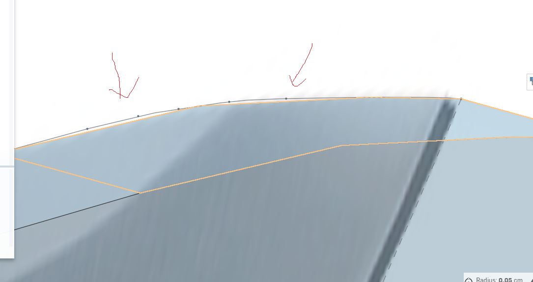
I need smooth spline, but if i take dwg, there are connected line at spline area. i am going to cut this with laser but i need smoother spline, how could i improve smoothness. you can see this at below. i can see stl file more smoother, if i open with fusion 360. But how can i use stl to get 2d drawing to cut laser.
https://cad.onshape.com/documents/445de3c05aaac8310613582d/w/40b9c1448a4f0558820148d7/e/e36c15054e10aa4a180cc347
I need smooth spline, but if i take dwg, there are connected line at spline area. i am going to cut this with laser but i need smoother spline, how could i improve smoothness. you can see this at below. i can see stl file more smoother, if i open with fusion 360. But how can i use stl to get 2d drawing to cut laser.

https://cad.onshape.com/documents/445de3c05aaac8310613582d/w/40b9c1448a4f0558820148d7/e/e36c15054e10aa4a180cc347
0
Comments
I'm finding exporting from a part and a drawing produce different results. Not sure why, but I think export from a part yields better results.
Today, I'm going to re-purpose a spline featurescript that I wrote a while back and have it tesselate the spline to create lines. This will give the facet control needed. If it works, I'll share it with you.
Ok, I got it, you can get to this through the fit spline featurescript. It should be available from Onshape in their featurescript area.
I did branch 'fit spline' and version it. You'll need V3.
A couple of things 1st, exporting from a partstudio & a drawing produce different results. Exporting a partstudio seems more robust. But, I want to do it from a drawing and this is what I'm trying to fix. My technique is to interpolate the spline into a polyline which I control. I'll show you how it works.
Exporting from a partstudio:
Exporting from a drawing:
I'm going to focus on the drawings from this point on.
So I start with this geometry, basic 4 splines:
Which produces geometry and a drawing that is wonky when exporting to dxf:
So to fix this, I interpolate the spline into polylines:
•tolerance is set to a 5mm facet depth which is really poor
•the seed curves are the 4 splines from my sketch
•added a create line option *new
•with this, you need to specify the plane I project everything onto to create a region
•don't have to click on show, it's a lot more stuff to display which you don't need
•I'm not closing the polyline so this can be left unchecked, it doesn't do anything for the create line option
The reason I create a region is because you can't window select curves once created and picking a thousands individual line segments is out of the question for me. The region is selectable for an extrude.
I pick the region formed by the polyline and extrude it. To help illustrate what's happening I show both shapes. 'Yellow' is the splines part which won't produce a drawing that exports dxf and the 'red' is a converted polyline part that currently is creating a poor representation of the yellow spline part:
If I drive the tolerance down to .1mm the whole story changes. Now you can see the 'red' part approximating the 'yellow' part more accurately:
The drawing of the 'red' part is now looking better. Since it's a bunch of lines, it'll export using dxf better:
I've tried everything trying to get a good quality edge from dxf and spline interpolation. Neither os or sw produced what I would consider an acceptable edge quality forcing me to generate my own interpolation. You should be able to drive the tolerance down until you blow something up. I do have a run-away loop control I use when debugging this algorithm. Without it, an error in the code, you can't stop os, it's an infinite loop. To prevent this, I've set this to 1000 try's which is a lot. If you hit this limit, it'll hit an error and throw a message like 'loop is out of control'.
Let me know if this works for you. Bottom line, you should be able to control the number of facets on the edge of your parts and dxf it out to your laser cutter.
Here's the error generated at a .01mm tolerance. Yours will vary based on curves. Click the featurescript brackets in the top os menu bar to see fs notices. Notice the error message 'loop out of control'. If you hit this let me know and I can up the resolution for you: