Welcome to the Onshape forum! Ask questions and join in the discussions about everything Onshape.
First time visiting? Here are some places to start:- Looking for a certain topic? Check out the categories filter or use Search (upper right).
- Need support? Ask a question to our Community Support category.
- Please submit support tickets for bugs but you can request improvements in the Product Feedback category.
- Be respectful, on topic and if you see a problem, Flag it.
If you would like to contact our Community Manager personally, feel free to send a private message or an email.
Writing FeatureScipts that use geometry not in a context?
 neobobkrause
Member Posts: 105 EDU
neobobkrause
Member Posts: 105 EDU
I seem to be missing something about writing FeatureScripts. A feature accesses a part studio's model by querying the context. I get that. What I'm confused by is that the geometry engine seems to only be able to work with geometric entities in the model -- and not temporary entities referred to by variables local to a function. Please allow me to set up the problem I'm struggling with by giving an example. (The current code can be found here.)
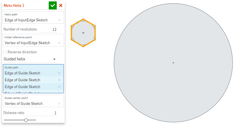
I'm developing a helix feature that has a mode that accepts a radius length, just like the builtin helix feature. In the feature I'm developing I refer to the mode that generates a helix using a radius as "Fixed radial" mode. But my "Meta Helix" feature will also have a "guided" mode that generates a helix curve with a distance and angle that varies based on a specified guide curve and optional center point. The screenshot below shows how guided mode accepts a "guide path" and "guide center point".
The path of the helix generated by this feature will revolve 16 times around is the edge of the circle. Note that the "Guided helix" mode of the feature has been chosen. In this mode the 6 sides of the hexagon are the "guide path", and the center of the hexagon has been selected as the "guide center point." This configuration will result in a helix that rotates 16 times around the outer circle curve. But instead of each rotation being a fixed distance from the helix path, the generated curve will be a hexagonal helix, kind of like this...
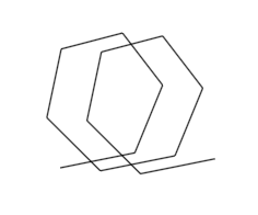
Get it?
The code that generates this guided helix differs from the implementation of the standard radius-driven helix because each control point of the generated spline isn't a fixed distance perpendicular to the input curve. Instead, a series of tangents from the guide center along the guide path are generated. (Note: the given guide path must be a closed curve.) Each turn of the generated curve will be based on one revolution along the guide path. (Just as is the case for the sample hexagonal helix shown immediately above.) So once an array of tangent vectors with an origin and direction along the input path has been created, and another array of vectors with direction and length are also created in the code, the process of generating control points for the helix is just a matter of doing a move transformation of each of the first array of vectors with each of the vectors in the second array, looping through the second array for every turn. Once an array of control points has been produced, it's passed to OpSpline. Done.
With the very simple design that I've described, it's evident that the default Fixed radius mode of my feature is equivalent to a guide path that is a circle having the given radius and a guide center point which is the center of that circle. But this is where I'm confused about how to write this code. My current code doesn't work because constructPath() wants a query that results in edges that a path is constructed from. It won't accept the circle I created "on the stack".
I get why queries are "safe" in this dynamic execution environment. But the circle that I created on the stack is also safe. I don't get why functions that do useful work, like constructPath(), won't accept my circle. More to the point, I don't understand how to design flexible code for both the modes of my feature that are able to share a common implementation.
Yes, I need a Meta Helix feature like the one I'm developing here for my own work. But it's also important that I use the development of this feature as an opportunity to learn FeatureScript. So I'm more interested in getting an understanding of the architectural questions I've raised here about queries and stack-based entities than I am in somebody "fixing" the implementation of my current code.
Thanks for any help.
- Bob
I'm developing a helix feature that has a mode that accepts a radius length, just like the builtin helix feature. In the feature I'm developing I refer to the mode that generates a helix using a radius as "Fixed radial" mode. But my "Meta Helix" feature will also have a "guided" mode that generates a helix curve with a distance and angle that varies based on a specified guide curve and optional center point. The screenshot below shows how guided mode accepts a "guide path" and "guide center point".
The path of the helix generated by this feature will revolve 16 times around is the edge of the circle. Note that the "Guided helix" mode of the feature has been chosen. In this mode the 6 sides of the hexagon are the "guide path", and the center of the hexagon has been selected as the "guide center point." This configuration will result in a helix that rotates 16 times around the outer circle curve. But instead of each rotation being a fixed distance from the helix path, the generated curve will be a hexagonal helix, kind of like this...
Get it?
The code that generates this guided helix differs from the implementation of the standard radius-driven helix because each control point of the generated spline isn't a fixed distance perpendicular to the input curve. Instead, a series of tangents from the guide center along the guide path are generated. (Note: the given guide path must be a closed curve.) Each turn of the generated curve will be based on one revolution along the guide path. (Just as is the case for the sample hexagonal helix shown immediately above.) So once an array of tangent vectors with an origin and direction along the input path has been created, and another array of vectors with direction and length are also created in the code, the process of generating control points for the helix is just a matter of doing a move transformation of each of the first array of vectors with each of the vectors in the second array, looping through the second array for every turn. Once an array of control points has been produced, it's passed to OpSpline. Done.
With the very simple design that I've described, it's evident that the default Fixed radius mode of my feature is equivalent to a guide path that is a circle having the given radius and a guide center point which is the center of that circle. But this is where I'm confused about how to write this code. My current code doesn't work because constructPath() wants a query that results in edges that a path is constructed from. It won't accept the circle I created "on the stack".
I get why queries are "safe" in this dynamic execution environment. But the circle that I created on the stack is also safe. I don't get why functions that do useful work, like constructPath(), won't accept my circle. More to the point, I don't understand how to design flexible code for both the modes of my feature that are able to share a common implementation.
Yes, I need a Meta Helix feature like the one I'm developing here for my own work. But it's also important that I use the development of this feature as an opportunity to learn FeatureScript. So I'm more interested in getting an understanding of the architectural questions I've raised here about queries and stack-based entities than I am in somebody "fixing" the implementation of my current code.
Thanks for any help.
- Bob
0
Comments
I think it might be because circles dont really have a start and an end.
Try creating two arcs.
Also, Could you share the document public, rather than via link (right click on the documents page and choose Make public)
IR for AS/NZS 1100
id you create them in a sketch? If you did, you need to solve your sketch before using them, then use qCreatedBy(sketchId,EntityType.EDGE);
IR for AS/NZS 1100
        var sketch1 = newSketchOnPlane(context, id + "sketch1", {
                "sketchPlane" : XY_PLANE
            });
        skArc(sketch1, "arc1", {
                    "start" : vector(0 * millimeter, r),
                    "mid" : vector(r, 0 * millimeter),
                    "end" : vector(0 * millimeter, -r)
                });
        skArc(sketch1, "arc2", {
                    "start" : vector(0 * millimeter, r),
                    "mid" : vector(-r, 0 * millimeter),
                    "end" : vector(0 * millimeter, -r)
                });
        skSolve(sketch1);
        const circle = qCreatedBy(id + "sketch1",EntityType.EDGE);
When integrated in, your code will look like this:
FeatureScript 847; import(path : "onshape/std/geometry.fs", version : "847.0"); /** * The type of helix mode. * @value RADIAL : Revolve a fixed distance from the helix path. * @value GUIDED : Revolve a varying distance from the helix path based on the relative distance * the given center point is from the . */ export enum HelixModeType { annotation { "Name" : "Fixed radius helix" } RADIAL, annotation { "Name" : "Guided helix" } GUIDED } annotation { "Feature Type Name" : "Meta Helix" } export const metaHelix = defineFeature(function(context is Context, id is Id, definition is map) precondition { annotation { "Name" : "Helix path", "Filter" : EntityType.EDGE } definition.helixPath is Query; annotation { "Name" : "Number of revolutions" } isReal(definition.revNumber, POSITIVE_REAL_BOUNDS); annotation { "Name" : "Initial reference point", "Filter" : EntityType.VERTEX, "MaxNumberOfPicks" : 1 } definition.refPt is Query; annotation { "Name" : "Reverse direction" /*, "UIHint" : "OPPOSITE_DIRECTION"*/ } definition.reversePath is boolean; annotation { "Name" : "Helix mode type" } definition.modeType is HelixModeType; if (definition.modeType == HelixModeType.RADIAL) { annotation { "Name" : "Radius" } isLength(definition.radius, LENGTH_BOUNDS); } else if (definition.modeType == HelixModeType.GUIDED) { annotation { "Name" : "Guide path", "Filter" : EntityType.EDGE } definition.guidePath is Query; annotation { "Name" : "Guide center point", "Filter" : EntityType.VERTEX, "MaxNumberOfPicks" : 1 } definition.guideCenter is Query; annotation { "Name" : "Distance ratio" } isReal(definition.ratio, POSITIVE_REAL_BOUNDS); } } { var guidePath; var guideCenter; var ratio; if (definition.modeType == HelixModeType.RADIAL) { var r = definition.radius; <a rel="nofollow"> <b>var sketch1 = newSketchOnPlane(context, id + "sketch1", { "sketchPlane" : XY_PLANE }); skArc(sketch1, "arc1", { "start" : vector(0 * millimeter, r), "mid" : vector(r, 0 * millimeter), "end" : vector(0 * millimeter, -r) }); skArc(sketch1, "arc2", { "start" : vector(0 * millimeter, r), "mid" : vector(-r, 0 * millimeter), "end" : vector(0 * millimeter, -r) }); skSolve(sketch1); const circle = qCreatedBy(id + "sketch1", EntityType.EDGE);</b></a> guidePath = constructPath(context, circle); guideCenter = box3dCenter(evBox3d(context, { "topology" : circle, "tight" : true })); ratio = 1; } else { guidePath = try silent(constructPath(context, definition.guidePath)); if (guidePath == undefined) throw regenError("Guide path is not a valid path", ["guidePath"]); if (!guidePath.closed) throw regenError("Guide path must be a closed path", ["guidePath"]); if (size(evaluateQuery(context, definition.guideCenter)) > 0) guideCenter = evVertexPoint(context, { "vertex" : definition.guideCenter }); else { guideCenter = box3dCenter(evBox3d(context, { "topology" : guidePath, "tight" : true })); } ratio = definition.ratio; } var helixPath = constructPath(context, definition.helixPath); const helixPathLen = evPathLength(context, helixPath); var helixPtCnt = hypot(evPathLength(context, guidePath) * ratio * definition.revNumber, helixPathLen) / (10 * millimeter); helixPtCnt = round(helixPtCnt + 10 * definition.revNumber); // var guidePathLen = evPathLength(context, guidePath); var guidePtCnt = helixPtCnt / definition.revNumber; var angleStep = 360 * degree / guidePtCnt; if (definition.reversePath) angleStep = -angleStep; var guidePts = []; var guideTangents = evPathTangentLines(context, guidePath, range(0, 1, guidePtCnt)).tangentLines; for (var currentTangent in guideTangents) { var pl = plane(currentTangent.origin, currentTangent.direction); var ln = line(project(pl, guideCenter), currentTangent.origin); var distance = evDistance(context, { "side0" : guideCenter, "side1" : currentTangent.origin } ) * ratio; guidePts = append(guidePts, currentTangent.origin + ln.direction * distance); } var helixTangents = evPathTangentLines(context, helixPath, range(0, 1, helixPtCnt)).tangentLines; var helixPt; if (size(evaluateQuery(context, definition.refPt)) > 0) { var pl = plane(helixTangents[0].origin, helixTangents[0].direction); var refPt = evVertexPoint(context, { "vertex" : definition.refPt }); var ln = line(project(pl, refPt), helixTangents[0].origin); helixPt = helixTangents[0].origin + ln.direction + guidePts[0]; } else helixPt = helixTangents[0].origin + perpendicularVector(helixTangents[0].direction) + guidePts[0]; var prevTangent = helixTangents[0]; var helixPts = []; for (var i = 0; i < helixPtCnt; i += 1) { var guideI = i % guidePtCnt; helixPt = rotationAround(prevTangent, angleStep) * helixPt; helixPt = transform(prevTangent, guideTangents[guideI]) * helixPt; helixPts = append(helixPts, helixPt); prevTangent = helixTangents[i]; } if (helixPath.closed) { helixPts = subArray(helixPts, 0, size(helixPts) - 2); helixPts = append(helixPts, helixPts[0]); opPoint(context, id + "initialPoint", { "point" : helixPts[0] }); } opFitSpline(context, id + "fitSplineSpiral", { "points" : helixPts }); });IR for AS/NZS 1100
Thanks for your input, but what you're suggesting actually adds a sketch with 2 arcs to the part studio. But the circle object in the example I'm using is "scratch geometry" that I want to use simply to calculate a series of vectors used to calculate the control points of the spline curve that the feature produces. I don't want my feature to add the circle to the studio.
Many graphics APIs have the ability to either create geometric entities that don't appear in the workspace or the ability to create "off-screen" workspaces. For example, I've done a lot of work with Rhinoceros/Grasshopper, which can produce literally 1,000's of intermediate results. Yet the only entities that are visible are those that you want to be.
I'm surprised to see that FeatureScript doesn't allow me to create a "scratch" context object that I could use to do these scratch computations and then enable me to move results entities over to the part studio's context.
Surely other FS developers have created design patterns for these implementation details. How are you all doing this?
- Bob
Thanks Jon, these are some of the best practices that I've felt that I've been missing. I'll look it over and give it a try.
There ought to be a section in the documentation that discusses these practicalities.
- Bob
Why did you break the circle I had into 2 arcs? If I leave my sketch geometry as a circle, then the path generated by constructPath() has 2 edges -- which are TWO circles rather than just the 1 I added. What's going on here?
Thanks,
- Bob