Welcome to the Onshape forum! Ask questions and join in the discussions about everything Onshape.
First time visiting? Here are some places to start:- Looking for a certain topic? Check out the categories filter or use Search (upper right).
- Need support? Ask a question to our Community Support category.
- Please submit support tickets for bugs but you can request improvements in the Product Feedback category.
- Be respectful, on topic and if you see a problem, Flag it.
If you would like to contact our Community Manager personally, feel free to send a private message or an email.
Assembly Constraint Problem: Mating a cylinder to a V-groove idler
 StephenG
Member Posts: 383 ✭✭✭
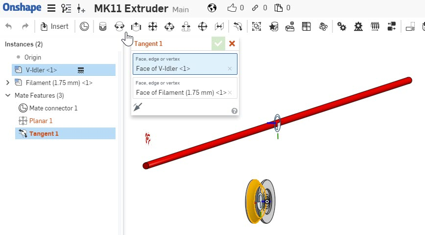
In theory just 2 tangent mates should do it: cylindrical surface of cylinder to each conical surface forming the V-groove.

I wasn't the least bit surprised Onshape had problems with this approach given the complexity of converging to a solution. I attempted to simplify the problem by first using a Planer mate to center the cylinder within the v-groove and constrain the cylinder's in-plane movement to keep it close to a reasonable solution. (The cylinder can move 5 to 20 in the green direction and +-15 in the red direction.)
The Planer mate worked fine, but when the Tangent mate was added to get the cylinder to move in the green direction to touch the V-groove conical surface OS chokes.
Any suggestions besides entering a hand calc to lock the green distance, or adding a Mate Connector to the V-groove idler part model at the "perfect" spot and using a Slider mate.
0
Answers
You can check this document
https://cad.onshape.com/documents/dbdea8442ddb2215d1ab994e/w/cfe853037e91f7f2a06ee587/e/311ec1c4097faafe62baea93
Eduardo Magdalena C2i Change 2 improve ☑ ¿Por qué no organizamos una reunión online?
Partner de PTC - Onshape Averigua a quién conocemos en común
Maybe I don't understand your question very well
Eduardo Magdalena C2i Change 2 improve ☑ ¿Por qué no organizamos una reunión online?
Partner de PTC - Onshape Averigua a quién conocemos en común
Yesterday I gave an in depth webinar on mating in Onshape. I am wondering if it might help you? Here is the link.
https://www.onshape.com/videos/onshape-assemblies-for-solidworks-users-071018
Normally, I watch (either live or recorded) all the Webinars (love them) but this appeared to be targeted to people with SolidWorks experience, which I lack, therefore, I skipped it. I will watch it today to see if I can pick up some pointers.
"My problem" is NOT being able to constrain the parts in question to produce the desired geometrical relationship with the desired residual degrees of freedom. My problem is that I had to employ a convoluted method to achieve the result. I could not use a mate method that aligned with how one would describe the relationship in simple words; no tangency mate was used to produce the desired result.
Even then, what I did wasn't perfect because it eliminates the axial rotational degree of freedom of the V-Groove part. I know how to address this, but I was satisfied the with "it looks good enough" result and moved on.