Welcome to the Onshape forum! Ask questions and join in the discussions about everything Onshape.
First time visiting? Here are some places to start:- Looking for a certain topic? Check out the categories filter or use Search (upper right).
- Need support? Ask a question to our Community Support category.
- Please submit support tickets for bugs but you can request improvements in the Product Feedback category.
- Be respectful, on topic and if you see a problem, Flag it.
If you would like to contact our Community Manager personally, feel free to send a private message or an email.
Why is this non-manifold? (No it isn't.) What's the quickest workaround?
 larry_sanders236
Member Posts: 4 ✭
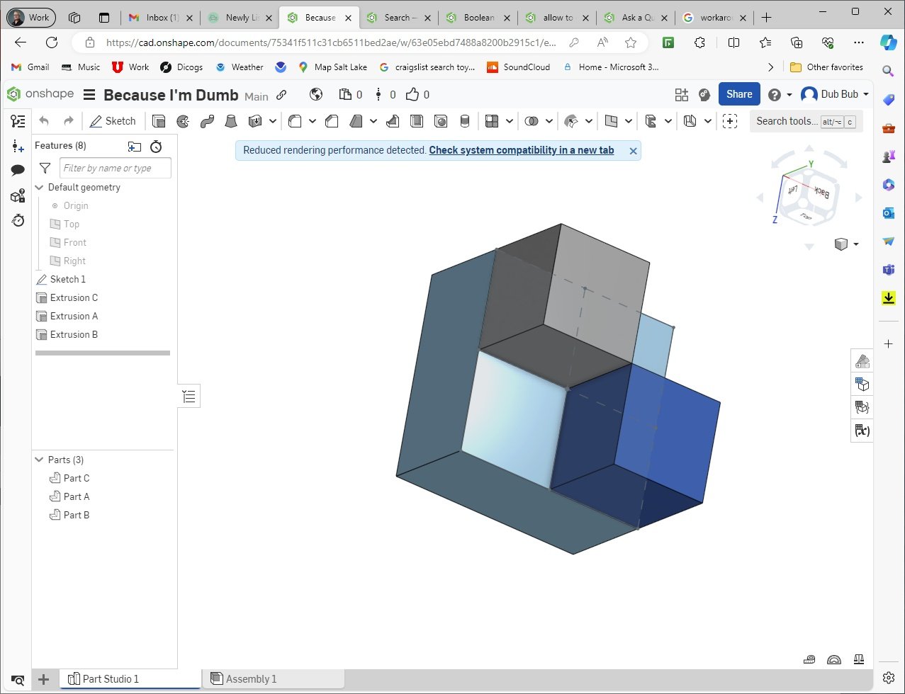
See this part studio.

I want to build parts from arrays of cubes.
The larger light-blue block is Part C and the two smaller cubes are A and B. A and B are not manifold to each other, but each can be manifold to C. I don't understand why a union of all three would not be manifold. If A and B are both manifold to C, the intersection between A and B should be of no consequence. What do I not understand about the meaning of "manifold"?
I see from my limited investigation many people have banged their head on similar non-manifold extrusions and unions, and that their existence is not tolerated by OnShape's kernel, and that from a machining perspective they are not realistic so why would I want to. I just do. But I'm not hopeful of this ever being supported in Onshape. So looking for workarounds.
Solutions I've tried or considered:
-Don't worry about it. Export multiple parts as one .step object and let my 3D printer think it's just one. Probably best and easiest solution, but my OCD sure doesn't like it.
-Put a tiny fillet or chamfer in the sketch I'm extruding, at the corners of the shapes sharing non-manifold edge, to either join or separate those shapes. This became a very detail-oriented task, ironically on a design that I want to lack detail. If the design consists of tens or hundreds of staggered cubes, this workaround could get labor intensive.
-Thicken: I don't like the idea of giving up the consistent precision between several blocks.
-(Just occurred to me) Use a linear array: Build a stack of cubes that have some fractional overlap, subtract the unwanted cubes, union the remainder. Oversize the source cube by some finite but invisible amount greater than the array grid spacing, so they all interfere with adjacent cubes. I like it!
OK thanks. Talking through this has really helped. Appreciate all your insights!

I want to build parts from arrays of cubes.
The larger light-blue block is Part C
 and the two smaller cubes are A and B. A and B are not manifold to each other, but each can be manifold to C. I don't understand why a union of all three would not be manifold. If A and B are both manifold to C, the intersection between A and B should be of no consequence. What do I not understand about the meaning of "manifold"?
I see from my limited investigation many people have banged their head on similar non-manifold extrusions and unions, and that their existence is not tolerated by OnShape's kernel, and that from a machining perspective they are not realistic so why would I want to. I just do. But I'm not hopeful of this ever being supported in Onshape. So looking for workarounds.
Solutions I've tried or considered:
-Don't worry about it. Export multiple parts as one .step object and let my 3D printer think it's just one. Probably best and easiest solution, but my OCD sure doesn't like it.
-Put a tiny fillet or chamfer in the sketch I'm extruding, at the corners of the shapes sharing non-manifold edge, to either join or separate those shapes. This became a very detail-oriented task, ironically on a design that I want to lack detail. If the design consists of tens or hundreds of staggered cubes, this workaround could get labor intensive.
-Thicken: I don't like the idea of giving up the consistent precision between several blocks.
-(Just occurred to me) Use a linear array: Build a stack of cubes that have some fractional overlap, subtract the unwanted cubes, union the remainder. Oversize the source cube by some finite but invisible amount greater than the array grid spacing, so they all interfere with adjacent cubes. I like it!
OK thanks. Talking through this has really helped. Appreciate all your insights!
0
Answers
Zoomed in to see the overlap.
At .011 OnShape accepted the overlap's existence.