Welcome to the Onshape forum! Ask questions and join in the discussions about everything Onshape.
First time visiting? Here are some places to start:- Looking for a certain topic? Check out the categories filter or use Search (upper right).
- Need support? Ask a question to our Community Support category.
- Please submit support tickets for bugs but you can request improvements in the Product Feedback category.
- Be respectful, on topic and if you see a problem, Flag it.
If you would like to contact our Community Manager personally, feel free to send a private message or an email.
Trying to Make a 2D Shape to Then Extrude
 tom_mort
Member Posts: 28 ✭✭
tom_mort
Member Posts: 28 ✭✭
I'm trying to make a clamping bracket that clamps around a round shaft. I have the shape I want in a 2D drawing consisting of a couple circles a couple of rectangles drawn with lines a small slice out of the circle and an area extending outward for a bracket.
My thinking was I could just join or merge or delete un-needed lines, etc to make a 2D shape that I could just extrude.
Here is a picture of what I'm trying to make and a screenshot of my drawing:

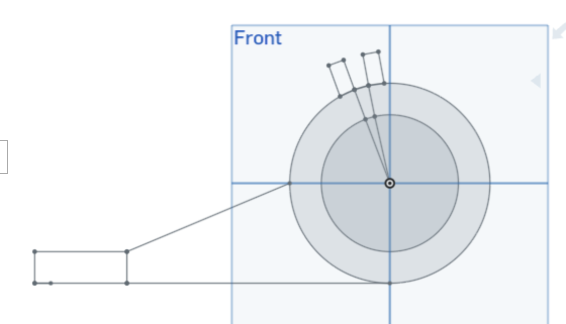
I found similar thread on using the trim tool or just to ignore any extraneous lines and just extrude the faces you want. I can extrude the ring just fine, but not the rectangular and other areas made with lines.
I'm new to Onshape and have used, but not very much and it was some time ago. It seems like making a 2D shape first and extruding it all at once would be simpler, but maybe I need to make some 3D rectangles and circles and then merge them somehow.
I'm sort of going in circles.
My thinking was I could just join or merge or delete un-needed lines, etc to make a 2D shape that I could just extrude.
Here is a picture of what I'm trying to make and a screenshot of my drawing:
I found similar thread on using the trim tool or just to ignore any extraneous lines and just extrude the faces you want. I can extrude the ring just fine, but not the rectangular and other areas made with lines.
I'm new to Onshape and have used, but not very much and it was some time ago. It seems like making a 2D shape first and extruding it all at once would be simpler, but maybe I need to make some 3D rectangles and circles and then merge them somehow.
I'm sort of going in circles.
0
Answers
Here is a screenshot zoomed in to the lines forming the rectangles and where they intersect the circle. It shows dots at the intersection lines. I figure that means they are connected. I know in some apps you can set things to snap to a grid or intersection, etc. I don't see anything like that here. I'm probably missing something. I know in pain programs you select the lines forming a perimeter and then can select a fill color or maybe there is a command to unite them.There are all sorts of tools with all sorts of names, usually not the terms I would use.
Also try dragging the end points around. If you can move them away from the intersecting line, they are not coincident.
Here is a sample that can be adjusted by changing sketch dimensions to get what you want.
https://cad.onshape.com/documents/feeafb87e93684b0f10c813b/w/ceb86e65fb96e6e9065eea91/e/19f5fd98fc3ac81ed58c3d79
The short answer to why every little change was saved was because I don't really know what I'm doing, trying to feel my way. When I go to sketch a small window appears that has a green and a red checkbox on it. I found if I selected the red one my sketch disappeared and if I selected the green one it my sketch stayed as I drew it and the sketch window closed. All the versions were annoying, but I selected the green not to save it so much as to close the small sketch window.
I did go to the learning center and it had a place to search on what it is I want to learn. I tried a number of things and then also just tried a web search while I was at it. I did get this thread here.
I also went and started a new sketch and figured out why my lines and circles weren't connecting or responding to the coincident tool. I had selected the top or the front plane. I saw there was another plane selection called origin if I remember correctly so I selected that. This time there were round marks that were shaded when I crossed a line and circle and when I ran the coincident tool something happened and I could select the face.
Like I mentioned I have used Onshape a few times for some very simple drawings, each time separated by a period of time of a year or more. I can't really remember very much of the details on how to do things to begin with and different drawings require different things. The one thing I so remember though is I get stuck on some small little detail like this and the frustration of it and my lack of vocabulary to ask a proper question. It's kind of like being shell shocked I suppose.
Thanks again for the help.
Link to CAD:
https://cad.onshape.com/documents/83b7229718662ca472446b17/v/16469754850614f01ebc873d/e/b95a9637d5d6bd437f700315
I learned a few things as well.
So in answer to my own questions and confusion I thought I’d add some things I learned doing this that I hadn’t seen mentioned when I was looking for how to do it..
I had been saving each step of each sketch resulting in many sketches. I thought I had to save the small sketch window after drawing each line, rectangle, circle, etc. I just did it to close the window.
Besides creating all sorts of versions, if I opened one of the saved sketches and tried to use trim or coincident, etc. the tools didn’t work. I suppose they will if you go into editing mode somehow, but I haven’t learned that. I learned that if I did draw one line after another things worked as they should.
I also discovered that if I drew a box one line at a time extending out from a circle they never connected, but if I did them one right after the other the connected and the faces formed by the intersecting lines automatically were both highlighted.
Good progress. A few comments:
Right clicking on a feature will allow you to delete it. If you abandoned a feature, delete it.
Double clicking on a feature in the tree will allow you to edit it. If a sketch, you can add more lines/delete lines, etc. If an extrusion, you can change its depth, etc.
The last several features in your tree are all to adjust the depth of the nut recess. Delete them all. Only keep the first extrusions for the nut. If the depth is not correct, double click on it and type in a new number for the depth. Don't keep making feature on top of feature for the same thing.
Good luck:)