Welcome to the Onshape forum! Ask questions and join in the discussions about everything Onshape.
First time visiting? Here are some places to start:- Looking for a certain topic? Check out the categories filter or use Search (upper right).
- Need support? Ask a question to our Community Support category.
- Please submit support tickets for bugs but you can request improvements in the Product Feedback category.
- Be respectful, on topic and if you see a problem, Flag it.
If you would like to contact our Community Manager personally, feel free to send a private message or an email.
Help with plan of attack on part modeling
 MDesign
Member Posts: 1,350 PRO
MDesign
Member Posts: 1,350 PRO
Since I am learning onshape and this part seems to have some geometry more advanced than my current skillset. I am wondering how others might attack modeling this part. I have started with half the base extrude and figured I'd just model half of it then mirror. I'm looking for opinions on where to go from here.


0
Best Answers
-
 S1mon
Member Posts: 4,127 PRO
Do you have the original part?
S1mon
Member Posts: 4,127 PRO
Do you have the original part?
Do you have access to a 3D scanner?
How accurately do you need to reproduce this part?
Is the back side of it flat, or is it mounted on a curved surface?
Can you tell how the part was made? (if it's a casting or molding, there will have been draft angles involved which can inform the modeling)If I had the original part and a 3D scanner, I would want scan data as a reference for modeling. Without a 3D scanner, but if I had the part, I would take some careful photos as orthogonal as possible to all the major directions with a really long lens to avoid parallax errors. I would also take as many measurements as I could with calipers.There's a main shape which is a cylinder which tapers into a tear drop. Then there is a decorative element which is offset. Everything appears to be mirrored across the axis of the cylinder. I would probably start with the main shape first. It would use a surface modeling approach and focus on the more geometric aspects first to define the relationships between the round hole and what I assume is a mounting surface.Simon Gatrall | Product Development, Engineering, Design, Onshape | Ex- IDEO, PCH, Unagi, Carbon | LinkedIn
2 -
 nick_papageorge_dayjob
Member, csevp Posts: 1,130 PRO
This is the type of part that is surface modeled. It's too complicated to discuss here. If you want to model it, go to the training center and do all the courses on curves first, and then surfaces.(curves are used to build the surfaces). I think it's about 6 modules. Anything in the consumer space that is organic shaped, or "curvy", is surface modeled.1
nick_papageorge_dayjob
Member, csevp Posts: 1,130 PRO
This is the type of part that is surface modeled. It's too complicated to discuss here. If you want to model it, go to the training center and do all the courses on curves first, and then surfaces.(curves are used to build the surfaces). I think it's about 6 modules. Anything in the consumer space that is organic shaped, or "curvy", is surface modeled.1
Answers
Do you have access to a 3D scanner?
How accurately do you need to reproduce this part?
Is the back side of it flat, or is it mounted on a curved surface?
Can you tell how the part was made? (if it's a casting or molding, there will have been draft angles involved which can inform the modeling)
Simon Gatrall | Product Development, Engineering, Design, Onshape | Ex- IDEO, PCH, Unagi, Carbon | LinkedIn
Yes I have part in hand.
No 3D scanner although thinking about buying one soon
Needs to be accurate enough to look at for the naked eye at 1/2 scale. not for tolerancing or anything special.... no holes needed just solid
backside will be just solid flat
its molded metal not draft angle needed. its cosmetic and will be cnc machined replica
I am using calipers for measurements.
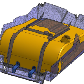
Here is how far I've gotten so far. 3 loft features so far. 1 for rib on top and 1 for the sloping curve and 1 for joining that to the slanted flat surface. If I can fill in that hole yet it's practically done except for filleting and mirror. The one thing I don't like is the way this fillet circled in red ends up being slanted instead of more perpendicular to the surface. Not sure what I can do there.