Welcome to the Onshape forum! Ask questions and join in the discussions about everything Onshape.
First time visiting? Here are some places to start:- Looking for a certain topic? Check out the categories filter or use Search (upper right).
- Need support? Ask a question to our Community Support category.
- Please submit support tickets for bugs but you can request improvements in the Product Feedback category.
- Be respectful, on topic and if you see a problem, Flag it.
If you would like to contact our Community Manager personally, feel free to send a private message or an email.
I need this like yesterday. Surface creation by 3d snap
 MDesign
Member Posts: 1,330 PRO
MDesign
Member Posts: 1,330 PRO
I've been working with scan data to create objects that fit that mesh data. Having never done this type of work before a few months ago. It's been a challenging experience developing a workflow to accomplish it, I've got a pretty good work flow figured out to keep the time down about as much as possible but just today I spent about an 1.5 hours working with curves to create a smooth loft surface to design a product against. Ever since I started down this path, I've always thought there had to be a tool out there that just let me create a surface by snapping to the mesh vertexes. It could cut my example time at least in half if not have it done in 15min (in my dreams I suppose).
Is there any custom features that do this or is there any work by onshape in the background on this front? Is there any other software that does this? Even if it was the only function of the software and it did it well by creating hard, smooth surfaces that onshape could use for modeling against, I'd go though that extra step.
Ideally I'd just like to snap to a series of vertexes in any order I choose to get a surface close to the mesh contour without the need for splines, profile this or profile that, guides . Sounds like a tall task but I'm no programmer. Being able to connect them together with tangent, fillets, etc would be a bonus.
Right now it takes a series of intersecting 3d splines to get the job done. if I miss an intersection that the curves are supposed to cross at OR i just don't like the curvature and need to adjust it, it takes fair bit of time to get that corrected and get the points in the proper order to get the spline(s) right.
I've been searching for a while for this and it seems like Mesh Snap recently released in Plasticity is getting pretty close with Constrained Surface Tool and Mesh Snapping

https://www.youtube.com/watch?v=c5FREB5BGzc
https://doc.plasticity.xyz/solid/constrained-surface
Comments
I think the edit curve feature just released today may help you out a lot.
just create some splines on some mesh points, create a boundary surface or loft with it, and create some edit curve features in between to tweak everything to your liking.
Oh my. Yes, Thank you, that is a much better workflow than I had to do before. Not quite what I had in mind for ideal, but that's gonna save a lot of time. with the current method.
Plasticity's constrained surface is apparently a Parasolid feature which they exposed. I suspect Onshape could do the same fairly easily if they wanted.
Simon Gatrall | Product Development, Engineering, Design, Onshape | Ex- IDEO, PCH, Unagi, Carbon | LinkedIn
@MDesign
Sounds like work similar to converting point cloud data to a mesh. In this case, maybe it is a cloud that is not real dense.
Maybe some of the links below can help.
https://forum.onshape.com/discussion/22643/what-to-do-with-a-point-cloud-in-onshape
In the link above, Neil mentioned MeshLab (a free open source program)
https://www.meshlab.net
Pay attention to the tabs at the top of the page when you get to the link
Never used MeshLab myself, but Google says it will convert point cloud info into a mesh
You also might want to look at using an iPhone to bring in LIDAR data directly into Onshape.
I think they want to. Haha.
my data is already in stl mesh format from a laser scanner provided by the client. I have to use mesh editing software to reduce/clean the data and get it to a managable size that doesn't choke onshape or my pc to death. I'll get multiple scans for a single project becuase of the nature of the project and small space you can't scan everything you need at once. And the files are often upwards of 100mb each. I have to cut them down to at least 10% of that to be able to import and work with them. What I'd like is to be able to do (for lack of better terminology) is trace over the stl mesh with surfacing and then design my parts against those surfaces.
From everything I've seen, MeshLab has tools made for getting a mesh down to a manageable size. In fact, that is what Neil suggested to be used for doing so.
This video shows it being reduced by changing one field.
https://www.youtube.com/watch?v=lHKOJ1dbyJI
By the time the football turns black (2 min. 10 sec.), I already see the triangulated mesh.
There are also smoothing tools in the program and tools for fixing holes
Looks like an extremely powerful program for dealing with points and meshes
But I can certainly understand you're wanting a more hands on approach, as I have done the same in the past.
@MDesign
Had a hard time getting the link posted above
Here it is
https://www.youtube.com/watch?v=lHKOJ1dbyJI
You may have misunderstood what my intention was. I have no desire to edit these mesh files in onshape if that's what I implied. I use other tools to do that. I've explored meshlabs well. Mesh editing tools are not the subject of my discussion here.
I obviously did. LOL
It sounded to me like what you were POSSIBLY trying to do was start with a point cloud. And then bring in JUST ENOUGH information of that point cloud converted to mesh, into Onshape, to where you could quickly set up an easily modifiable surface using Onshape’s toolset.
My thinking was in that trying to do as much work in MeshLab as possible, that when in Onshape, you wouldn’t be working over a heavy mesh which can be no fun, especially when the back parts of a mesh are getting hard to differentiate from the front parts of a mesh.
So I was thinking that possibly by refining, downing sizing points, and smoothing as much of that mesh within a program like MeshLab as possible, that the highly simplified mesh, would possibly be easier for snapping to, when in Onshape.
A whole lot of guessing on my part as to what you were possibly trying to accomplish !!!
Anyways, sounds like you have it under control. So just excuse my blather. LOL
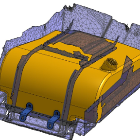
Haha. No worries. Been there done that. Thanks for explaining. I refered to mesh data as a surface. Never thought of point clouds as being interchangable terms with mesh data. Here's screen shot of where I start in onshape with mesh data. My goal is to fit a fuel tank under that seat.
Welp… looks like what I needed was just hidden in plain sight all along. 🤦♂️Only thing that would make it better would be not having to define the edges of the surface and they'd just be created on their own from the outermost points .
Yes, Fill has had the ability to add guides (points or curves) all along. However it is completely different code/algorithm than the other one mentioned earlier in this thread.
@MDesign:
have you played around with feature scripts yet?
what you suggest should not be too hard if you take code from the native features as a starting point?
just that when everything is in one feature, "edit curve" as a native feature won't fit in between.
integrating that as well may make it too elaborate and make it less usable.
this way of using fill will not create good quality surfaces.
it seems to me you're mostly worried about a lightweigth spatial reference and the quality of the surface isn't that critical. so than it will do.
Correct. surface quality is of no concern with what I typically need. If it does become a concern I will use curves and lofts, etc. I use this surface to cut other geometry against to provide tight tolerance fitment of objects against it. I have not explored feature scripts yet. I do have some script programming background in other contexts but haven't taken the time yet for onshape.
With your Fill approach, quality is one thing (and yes it will be quite bad), but performance will likely be even more of a concern. With the boundary and the guide points, there is a lot going on in order to fit a surface. When things get so constrained, the underlying math gets more and more hectic…
@MDesign would you be willing to DM me the mesh to try some things out in Rhino? I'm curious if a workflow like this might work:
You certainly can do as you're suggesting with Fill as well. Greg is right that performance will be atrocious, though I'd think of it as a pre-processing step, that doesn't need to be parametric. You could do your ugly, heavy fill surfaces, then export and reimport it to make it static again.
The Onsherpa | Reach peak Onshape productivity
www.theonsherpa.com
Hmmm… That's interesting. I may have to switch to Rhino. 😮 I'll send you a link to one in a DM.
The way I use it It's more of a swiss army knife to supplement Onshape, but Onshape is by far my main tool. I wouldn't use it to try to get something to production. "Switching" to it makes as much sense to me as switching to a spatula from a chef knife, but they can complement each other.
The more I've thought about your challenge though, I'm curious why you need surfaces anyway? Onshape's mixed modeling is awesome, and it sounds like you're just using the mesh as a general spatial reference, not a tight tolerance thing. Can you say more about the desire to make it into surfaces?
The Onsherpa | Reach peak Onshape productivity
www.theonsherpa.com
I said "switch" a bit tongue in cheek. I agree each software has its own pros and cons and can be used to compliment each other. But if that software allows me to do something that I do often but in less time, it makes sense to do it there. I will be exploring QuadRemesh in the near future for that reason. Thanks for sharing.
If I have surfaces which onshape can use/manipulate to start with I don't need to create planes, sketches, and surfaces from scratch, just so I can model against them. I can use the surfaces to model geometry to rather than creating complex surfaces first so that I can model 'up to' to them later. For example if I need to split an object to create some irregular space on one of its faces…. I need to create that complex surface (referencing the scan data) with onshape tools to do that split so that I can provide that space between objects with an offset surface, move face or similar. Yes I can split the object with the scan but really can't do much else to that face after that. Its kinda stuck in the condition it is at the time of the split.
Also the use case exists that when a product goes through a revision and gets rescaned. a new STL file with the changes are provided. importing the new geometry takes some time to setup and align to the existing model and then creating. The revised geometry can be massaged to the new scan of those new surfaces, where as you cannot create a solid "up to" a mesh surface with an offset. I need to create a plane or surface (if its complex) to model to it so that I can accomplish that particular task.
Also I know there are requests for smooth surface models from scan data so that people can do mixed modeling or 3d print something with better surface quality than the file they downloaded. The time/cost to convert them seems to scare em. LOL
Its a work in progress trying to learn the best way to work with these scans that are not "solid". mixed modeling definitely plays a part when the scans are solid. But not really a factor for these scans that are simply representing various unconnected surfaces of the space via a bunch of triangles. It's definitely not a tolerance issue for me, just searching for ways where it doesn't feel like I"m reinventing the wheel so to speak (aka creating a surface that already is represented in the mesh data).
FWIW I fairly green to surface modeling and have a come a long way… so I'm learning new methods quite frequently and exploring new ideas to improve workflow.
Got it. In this case I think of Rhino as a pre-processing tool like someone would use Meshmixer or Blender. It could be great for that. If you end up doing it a lot you could create macros or use Grasshopper to streamline your preprocessing workflow. You might even find that Meshmixer to Rhino to Onshape is valuable.
My instinct is still to avoid directly referencing the mesh (or the surface converted to nurbs from Rhino). The surface quality is still poor enough to cause downstream issues with offsets, thickens, shells, etc. And this workflow is worse if you expect to later get an updated stl since you'll have to re-do all of the preprocessing steps again, and it will break all of your Onshape references when you import the new one. To that end, the best way I think is to make as few direct references to the scans as possible. You would be better off making a few key datums (key planes, mate connectors, and sketches) that reference it then hanging the rest of the design on those datums. That way if you break references you only have a few to reattach. This does imply that you're going to manually re-create some of the surfaces in a way that keeps them simple and 4-sided. Nurbs surfaces are all 4-sided mathematically, even if they are trimmed into something else later, or one of the "sides" is actually a point (like the pole of a sphere).
The Onsherpa | Reach peak Onshape productivity
www.theonsherpa.com
referencing is not an issue with this type of work on STL's becuase onshape doesn't update anything when the STL moves or changes. I suspect that would be a significant performance hit if it did. When a new STL is done, yes I have to redo the preprocessing on new scan data, can't get away from that. but sometimes I'll just isolate the geometry that changed to preprocess. For simple revisions I'd probably just leave STL as is and model to it as reference, not really worried about any linking issues to the reference since its static in most of my cases. so downstream is not really of concern. but maybe someday that case could be made as tools and processes develop. The added advantage of having a nurbs surface come in vs the STL mesh is that I could potentially manipulate the surfaces as needed (bridge gaps and such) and create say an offset surface from it as a starting point vs trying to model all the nooks and crannies from scratch that may exist.