Welcome to the Onshape forum! Ask questions and join in the discussions about everything Onshape.
First time visiting? Here are some places to start:- Looking for a certain topic? Check out the categories filter or use Search (upper right).
- Need support? Ask a question to our Community Support category.
- Please submit support tickets for bugs but you can request improvements in the Product Feedback category.
- Be respectful, on topic and if you see a problem, Flag it.
If you would like to contact our Community Manager personally, feel free to send a private message or an email.
Drafting two faces not symmetrical
 graham_lock
Member Posts: 265 PRO
graham_lock
Member Posts: 265 PRO
Hi,
I'm applying a draft to a frame.
The draft is applied to two opposite faces and I was expecting that each face would be drafted by the same amount, but they're not.
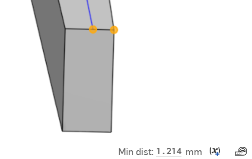
The frame starts as a 6mm square, the blue line is the frame reference line:


The draft is applied as below, the neutral plane is the opposite end face.

The results are as below:

I'm sure I'm missing something.
Any help appreciated.
Thank you.
Best Answer
-
 jelte_steur_info
Member Posts: 655 PRO
jelte_steur_info
Member Posts: 655 PRO
Hard to tell without looking at the document…
Could you perhaps share a document with an export of these parts only? (we've seen them already).is the blue line not straight? then perhaps the whole frame is not straight? if the whole beam is slightly bent, the draft would take less from the convex side, and more from the concave side? what could cause a frame to be bent? strange…
The most logical cause i could speculate is that during the rotation (what axis are you rotating around?), the frame is shifted out of perpendicularity from the 'neutral plane' that determines the draft direction and could cause the uneven draft.
This could be tested by drafting with a parting lines where you'll be able to set the draft direction by hand.but as it seems to me, the draft may be aplied well, but your blue center line is not accurate, so the problem is with the line, not the draft…
0
Answers
Can you share a document? Could be that that blue line is misaligned after the draft. If the part is extruded, can you draw it with the draft built in instead?
Thank you, it’s not an extruded part but a frame.
The draft will form part of a Featurescript where it’s behaving as per the example above.
I initially tried using sketches and extrude but sketching in FS broke easily and I note that OS don’t recommend sketching in FS.
I haven’t managed to replicate the issue in a test document.
I can’t share the project document unfortunately so any guidance as to what may be happening would be gratefully received.
Thanks again.
It turns out that the frame reference line had a very slight downward bow near its centre.
Once this was straightened the draft works as expected.
Why would such a deviation cause the draft to have an offset?
Thank you.
The problem only occurs if the beam is rotated:
In my use case the beams are place around the edges of former parts - before the draft is applied all looks fine:
After the draft is applied:
The centre line is now distorted.
If the beam sits at the top pf the formers at 0 deg there is no distortion after the draft.
Any advice appreciated.
Thank you.
Hard to tell without looking at the document…
Could you perhaps share a document with an export of these parts only? (we've seen them already).
is the blue line not straight? then perhaps the whole frame is not straight? if the whole beam is slightly bent, the draft would take less from the convex side, and more from the concave side? what could cause a frame to be bent? strange…
The most logical cause i could speculate is that during the rotation (what axis are you rotating around?), the frame is shifted out of perpendicularity from the 'neutral plane' that determines the draft direction and could cause the uneven draft.
This could be tested by drafting with a parting lines where you'll be able to set the draft direction by hand.
but as it seems to me, the draft may be aplied well, but your blue center line is not accurate, so the problem is with the line, not the draft…
@_anton and @jelte_steur814, you're both absolutely correct, the blue line is not accurate.
That line is a 3D Fit Spline generated in Featurescript with vertices at a given % offset along the selected edges of each of the formers.
The frame is drawn at an angle which is tangent to the selected edge on the first former where the blue line intersects that edge so the rotation is constant throughout the frame,
If the angle of the beam as viewed from the side is not constant throughout its length, ie maybe it bends down towards the end, then the blue line essentially shifts across the beam as viewed from above leading to the draft offset.
At least I can see what's happening now!
Thank you for your help.