Welcome to the Onshape forum! Ask questions and join in the discussions about everything Onshape.
First time visiting? Here are some places to start:- Looking for a certain topic? Check out the categories filter or use Search (upper right).
- Need support? Ask a question to our Community Support category.
- Please submit support tickets for bugs but you can request improvements in the Product Feedback category.
- Be respectful, on topic and if you see a problem, Flag it.
If you would like to contact our Community Manager personally, feel free to send a private message or an email.
Strange behavior of sketches when changing the inclination of the plane.
 sergei_nesterov
Member Posts: 45 ✭✭
sergei_nesterov
Member Posts: 45 ✭✭
Good day!
Several times I have encountered a situation when when changing the angle of inclination of the plane, the snapping of elements in the sketch also changes. It seems that the coordinate system is changing. Made a test drawing : https://cad.onshape.com/documents/c26191c81cd466de29cce6c8/w/cdce6d872533fd8340e131ee/e/934c6004ff8915dd87dc10e3
A normal sketch at an inclination of 47 degrees :
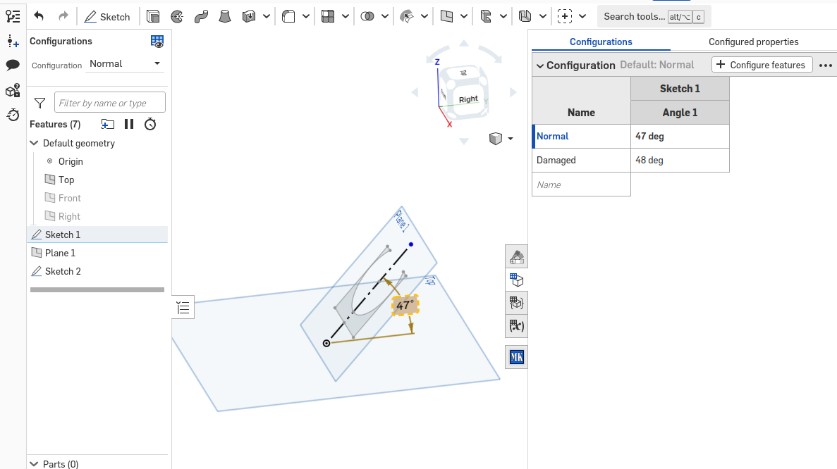
But at an inclination of 48 degrees, the plane rotates 90 degrees relative to the axis and the sketch elements are displaced. At the same time, the variable angle of inclination should not affect the rotation of the plane around the axis in any way.
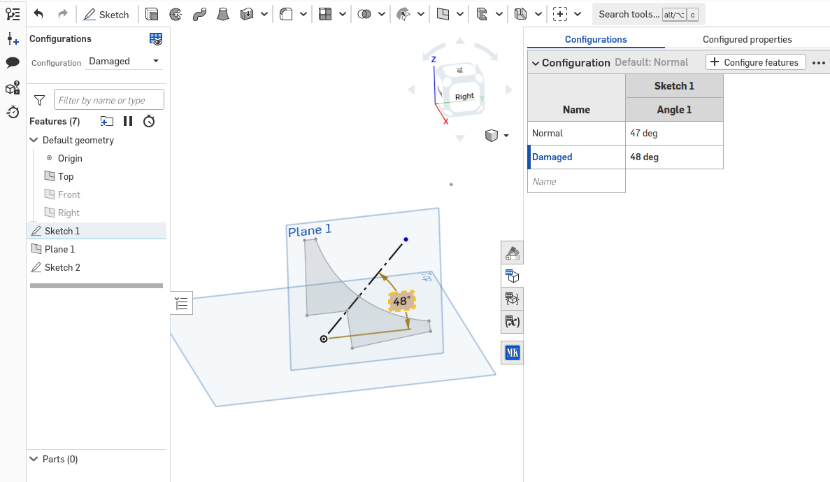
There were cases where the plane remained in the correct position, but the sketch changed orientation by 180 degrees, destroying the integrity of the depicted structure.
I do not understand such behavior, especially with such banal angles as 47-48 degrees (this is not 90 or 180). At the same time, in my model I cannot avoid them. Please explain what is happening and how to get out of such a situation.
Comments
In the
Plane 1feature you should add theTopplane as an additional reference to disambiguate the normal direction of the plane you are creating.Thanks for answer! It works. But I don`t understand why. The Plane definition requires only a Line and the Angle. In addition, the link of the Plane 1 to the Plane Top occurs through the Sketch 1. In this sketch, the angular size connects the line and the Plane Top. Nowhere to indicate the presence of ambiguity. I did what the interface asked, selected a Line and the Angle. Does this situation described in the Learning Center ?
A really good way to deal with this is to use a mate connector instead of a plane. That way you have full control over the sketch axes
I hadn't run across that info yet in any learning resource. It's probably out there but I only stumbled across it by mistake clicks and discovered it more rigidly defined the planes with the help of "helper" objects/references.