Welcome to the Onshape forum! Ask questions and join in the discussions about everything Onshape.
First time visiting? Here are some places to start:- Looking for a certain topic? Check out the categories filter or use Search (upper right).
- Need support? Ask a question to our Community Support category.
- Please submit support tickets for bugs but you can request improvements in the Product Feedback category.
- Be respectful, on topic and if you see a problem, Flag it.
If you would like to contact our Community Manager personally, feel free to send a private message or an email.
Help with mating options
 shannon_gomes653
Member Posts: 7 ✭
shannon_gomes653
Member Posts: 7 ✭
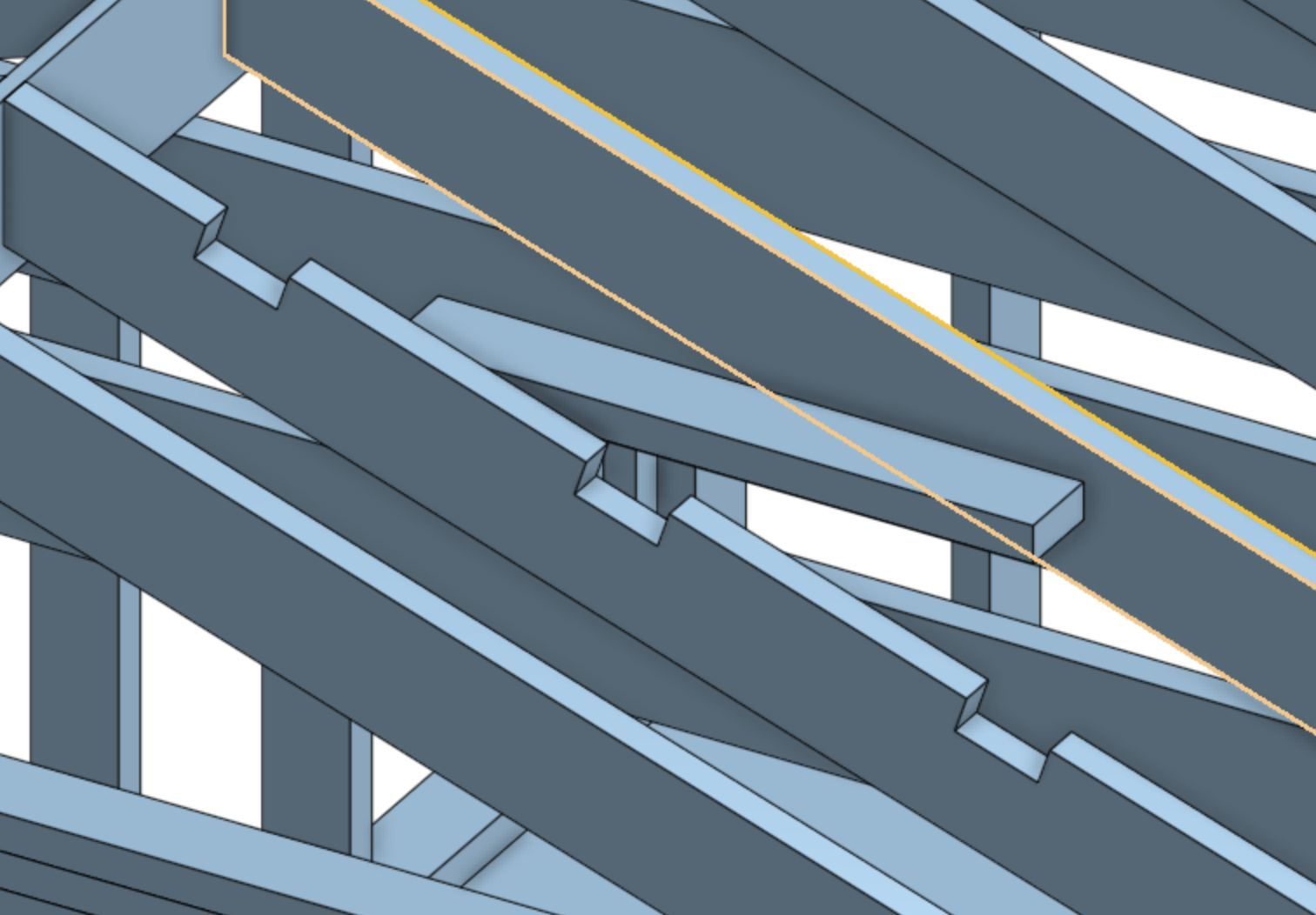
I thought I was doing pretty good with mates until I ran into this issue. In the image below, I want to place the short piece into the notch shown and also mated with the face of the highlighted part. I tried a planer mate with the bottom of the notch. ok. Then another planer mate with one side of the notch. So far so good. I can slide the short piece back and forth in the notch. Almost there. Then I tried another planer mate with the highlighted piece. That blows the assembly apart. I've tried a bunch of different ways of doing this but I'm stumped.
Answers
If the short piece if meant to be centered on the notch, you just need one fastened mate between the center face of the bottom of the notch and the middle of the short piece.
Using multiple planar mates to locate a par is almost never the "correct" way of doing it in Onshape.
Like this:
I understand that part but it is not supposed to be centered end to end. One end of the piece needs to be flush with the part I highlighted in yellow. So in the notch as you showed AND against the other part.
Hey Shannon. You could measure the distance between the notched rafter and a neighbor rafter, add half the thickness of the rafter and place a mate connector accordingly on the piece, using the dimension as an offset in X or Y, whichever applies. If you need to fasten the other pieces in the image in the same way, the calculation you arrived at could be placed in a variable for repeated use. - Scotty
You could use a slider mate in the notch and a planar mate at the end against the first rafter. but 3 planar mates should work fine as well. If its blowing apart, perhaps something needs fixed in place or is not constrained enough relative to something else that's fixed.
Three planar really isn't the best way as it may end up causing an error even when it "should" work as it is over-constraining the rotations.
I see, you could use an offset in the mate, or probably the most robust option (that should tolerate some mis-alignment) would be to use a width and a slider:
Actually I realized you only need 1 selection in the width mate if you want to limit "over-constraining".
@eric_pesty Curious, why do you say 3 planar mates are over constraining? (disclaimer: not super well versed in assembly mates yet regarding larger projects) Don't the other solutions essentially constrain in 3 directions also even though your only using 2 mates?
@MDesign
Each planar mate constrains the rotation of the part to that plane so the different ones are "fighting".
I don't think any rotation is desired by the OP.
As the previous commenter mentioned, setting offsets would be ideal for the fewest number of mates and the simplest assembly.
Perform a fastened mate on the face, which will be planar with the notch in the larger truss, and then measure the exact offset needed by clicking on the two parallel faces (end of the small beam, and the face you want it to be planar with). Then, edit the fastened mate and create an offset with the specified distance.
Hope this helps!
Thanks for the help everyone. The 3 planer mates to me makes the most sense coming from a Solid Works workflow. You keep adding mates until the part is fully constrained. I guess Onshape doesn't use that methodology.
In this case I guess the slider mate with a planer end-face mate makes the most sense? I get the offset method but "philosophically" that isn't very good. If spacing changed the mates would break. I could parameterize it based on the rafter spacing I guess.
I am curious why the "adding mates until it's fixed" methodology isn't used by Onshape. Seems really intuitive.
Work with it for a while. You'll find he OS method becomes faster and easier to under stand.
Spacing won't break if it's done with and array. Just set number and spacing from the original part. All in one feature. If you learn about variables and variable studios the numbers can be changed for all assemblies. Your next step may be to study in context editing to make one off copied parts the the rafter edit a cut out a new part with the cut out and the cross over board. When the context is up dated any parts referencing existing parts context parts will up date as well. Your cross board for example would be sketched on the face of one rafter and extended to the face of the next.
I've worked with a few systems ( Solid Edge/SolidWorks/Inventer and probably more) that used 3 mates per connection and found it tedious and at times a bit of a pain. With Solid Edge only 2 mates were needed to place a bolt and that left and error message that couldn't be eliminated.
The Onshape way definitely takes some getting used to but it's well worth getting familiar with it. You will need to get familiar with editing mate connectors to get the most of out of it.
I have a video series on mates and mate connectors going over topics that I find aren't well explained in the Onshape docs… The interface has changed a bit since but it's still relevant:
https://www.youtube.com/watch?v=HUVFq7tixKM&t=4s
I would also recommend watching this excellent video from Evan:
https://www.youtube.com/watch?v=w5wY8TWjjd0
The beauty of the Onshape method of using only one mate between two parts (in 95% of cases) is that you don't run into conflicting mates nearly as much, and it's much easier to fix issues when they come up.