Welcome to the Onshape forum! Ask questions and join in the discussions about everything Onshape.
First time visiting? Here are some places to start:- Looking for a certain topic? Check out the categories filter or use Search (upper right).
- Need support? Ask a question to our Community Support category.
- Please submit support tickets for bugs but you can request improvements in the Product Feedback category.
- Be respectful, on topic and if you see a problem, Flag it.
If you would like to contact our Community Manager personally, feel free to send a private message or an email.
Cannot Hollow Out Airplane Wing in Onshape
 Soapydog
Member Posts: 2 ✭
Hi,
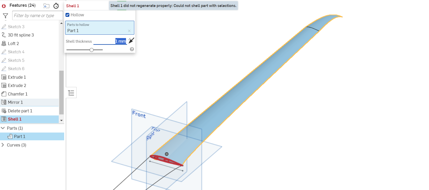
I am relatively new in CAD modelling and Onshape, so please forgive me if I do something wrong. I am trying to hollow out an airplane wing using the shell tool with thickness of 1mm. However, it just says "Shell did not regenerate properly: Could not shell part with selections."

When I use the shell feature on an object without any loft, it works just fine.
The Onshape Project in question is linked below:
https://cad.onshape.com/documents/095333f1d5648663e6ed9298/w/613a00502683658c17564057/e/66be12b516ee5376dd0fdbc5?renderMode=0&uiState=65f4267ecdc0954490e68e50
Would Appreciate any assistance,
Soapy dog


I am relatively new in CAD modelling and Onshape, so please forgive me if I do something wrong. I am trying to hollow out an airplane wing using the shell tool with thickness of 1mm. However, it just says "Shell did not regenerate properly: Could not shell part with selections."

When I use the shell feature on an object without any loft, it works just fine.
The Onshape Project in question is linked below:
https://cad.onshape.com/documents/095333f1d5648663e6ed9298/w/613a00502683658c17564057/e/66be12b516ee5376dd0fdbc5?renderMode=0&uiState=65f4267ecdc0954490e68e50
Would Appreciate any assistance,
Soapy dog


0
Best Answers
-
 martin_kopplow
Member Posts: 1,195 PRO
Yeah, that's a difficult shape. It might be a good approach to surface-model that, maybe keep top and bottom separate at the chord for now, and then thicken, unite.
2 -
 john_lopez363
Member Posts: 140 ✭✭✭
@Soapydog
Here is one approach! Perhaps not ideal, but it's a work around.
- Create a second set of airfoil profile sketches that is somewhat smaller than the originals. You will need to create the root profile sketch offset from original so that you can retain the notch and tab you've modeled.
- Loft Remove using the smaller profiles sketches.
0 -
 rick_randall
Member Posts: 412 ✭✭✭
martin_kopplow said:Yeah, that's a difficult shape. It might be a good approach to surface-model that, maybe keep top and bottom separate at the chord for now, and then thicken, unite.I'm with martin on this one. Start with inside profile, loft as a surface, and then thicken. With airfoil shapes, I can tell you the problem issues always seem to show up at the trailing edge ( usually in the form of self-intersecting profiles). working from inside to outside will eliminate most of these issues ( but not always). Also use guide curves with lofts - this seems to make lofts more stable. And as Nick states - model with tiny radii on trailing edges.Keep going, you will get there. Just wait till you try propellers lol.1
Answers
Even for an experienced user, which I consider I am, this is a difficult shape to work with.
I tested some approaches with a copy of your model and I'm not sure you will be able to hollow it.
@martin_kopplow wrote, a surface-model approach is the best way to go.
Here is one approach! Perhaps not ideal, but it's a work around.
- Create a second set of airfoil profile sketches that is somewhat smaller than the originals. You will need to create the root profile sketch offset from original so that you can retain the notch and tab you've modeled.
- Loft Remove using the smaller profiles sketches.
Same problem here. This is the link to a pretty minimal wing panel (re-)demonstrating the problem:
https://cad.onshape.com/documents/d3de070507e43aeaf80b85b0/w/21a6706159cfe814ee972203/e/7130d5b3acbdb42e52af6d15?renderMode=0&uiState=68c312635136fd309f05c48d
https://us.v-cdn.net/5022071/uploads/BISD7UEDC8AP/image.pngThe suggested solution of designing two surfaces and thickening them from inside-out is not really a good solution IMHO, as this approach modifies the curvature of the chosen airfoil. Modern airfoils are designed very carefully here and there will be definitely a performance penalty when going this route because the CAD system used can't do better.
The other suggestion of removing a smaller inner wing panel is also not really helpful when trying to 3D-print a wing panel, as this leads to non-constant perimeter layer thickness and hence to lots of unwanted slicing artifacts.
I just cross-checked Fusion360 - it is flawlessly able to shell the body exported form the above document, despite the performance is quite awful. This is also my current work-around: export from Onshape, shell it in Fusion - reimport to Onshape. But this workflow kind of sucks and negates any advantages of a parametric design approach.
Any other ideas how to work around this problem? Any help would be really appreaciated.
Thanks,
Holger
Maybe make it so that it doesn't come to an absolute point. I suspect there are zero manufacture-able wings that end in a point like yours does.
@holger_steinhaus
You're not supposed to start the 'inner' airfoil with a scaled-down version of the original, for that would indeed compromise the curvature, but with an offset.
That said, you could also make the original as usual, then create offset surfaces at the inside and use these to make an enveloped volume to bool away. Still, it stays true: There is no razor sharp TE in real life. And in my experience, there are no (or in fact fery few) one-piece-wings out there. It happens to be that I am a maker of one type of those rare one-piece wings, but that requires a proprietary technique to put the spars in. Trust me, you want to avoid that. That said, it makes little sense to design a wing on one piece, but rather design the parts you're going to manufature to assemble the wing from, even if it is a composite wing: Even these will usually not have a constant wall thickness.
The zero-thickness trailing edge is the work-around to make the loft compute correctly. Using a 1mm trailing edge, it is no longer possible to loft along the guides into a single point, which is required for the intended design.
Thanks, @martin_kopplow, I think now I got it: generate the airfoil sketch, minus-offset the edges it by shell thickness, loft the surface, plus-thicken the surfaces it by the same amount. Very good idea, indeed!
The razor-sharp trailing edge is unfortunately required to make the loft along the 3D-projected curve succeed - at least I did not find a better solution yet. I would prefer a defined width of the TE indeed.
The 3d-printed wing panel is an idea that I am very curious about. There are quite a few (successful) examples on the Internet going that road. I think, a 1.5mm shell plus some diagonal ribs printed in place, plus a of-the-shelf carbon fiber tube as a "spar" could work reasonably well for a 1.2m wingspan model aircraft.
It can be done without razor edge, but might take a bit more effort and a different approach. I don't have time to make an example right now though.