Welcome to the Onshape forum! Ask questions and join in the discussions about everything Onshape.
First time visiting? Here are some places to start:- Looking for a certain topic? Check out the categories filter or use Search (upper right).
- Need support? Ask a question to our Community Support category.
- Please submit support tickets for bugs but you can request improvements in the Product Feedback category.
- Be respectful, on topic and if you see a problem, Flag it.
If you would like to contact our Community Manager personally, feel free to send a private message or an email.
Export to 3mf does not export the NPT thread
 marc_van_camp
Member Posts: 6 ✭
marc_van_camp
Member Posts: 6 ✭
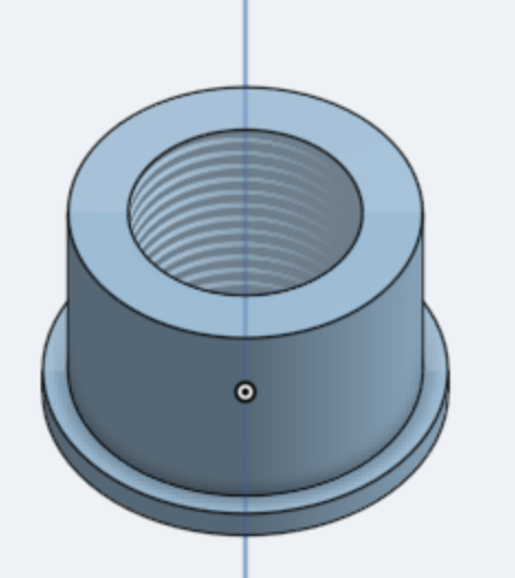
I've created a simple model, with a hole tapped with NPT 3/4" - 14 TPI. I need this 3D printed, so exported in to 3mf (Prusa slicer). In the Prusa slicer the thread is not modelled.
Questions:
1: what am I doing wrong to get the thread exported?
2: why is the thread not tapered in the design in onshape (bottom diameter is samen as top diameter!).
Many thanks for your feedback.
Marc
Best Answers
-
 Derek_Van_Allen_BD
Member Posts: 611 PRO
Derek_Van_Allen_BD
Member Posts: 611 PRO
You've used a cosmetic thread feature which only applies a decal to the face of the object. The custom features I'm aware of that do modeled threads don't support NPT thread geometry so what I do instead is download a McMaster Carr part that has the thread geometry I want to borrow, cut away anything that isn't relevant on that model and derive it into my part studio to use with a boolean feature.
3 -
Derek_Van_Allen_BD
Member Posts: 611 PRO
You seem to have found one of the rare few parts in the mcmaster carr catalog modeled with straight threads instead of the correct NPT geometry. CAD manager must have been asleep that day. I went and pulled one from the elbows catalogue which has better thread models I've validated with my own 3d prints. The way I approach models like this is to get a single studio cooked up with the features I want to use on other models and to use it as a seed for the Point Derive custom feature so if I need to make changes to my clearances or geometry for this 3/4" NPT geometry later I just need to update the source studio and it'll force downstream updates anywhere it's used. Think of it like a geometry catalog instead of a parts catalog.
1
Answers
You've used a cosmetic thread feature which only applies a decal to the face of the object. The custom features I'm aware of that do modeled threads don't support NPT thread geometry so what I do instead is download a McMaster Carr part that has the thread geometry I want to borrow, cut away anything that isn't relevant on that model and derive it into my part studio to use with a boolean feature.
Derek Van Allen | Engineering Consultant | MeddlerThat's a good trick!
In a more general answer to question 2:
By default threads are not modeled. On large assemblies or parts with many threads they slow down the software. Traditionally 3D models are used to create eng drawings to be used for 'subtractive' manufacture.
On eng drawings threads are represented by thin parralel lines either side of the thread for a side view, or a broken circle for an end view. Threads are not drawn, because eng drawings used to be done by hand and drawing threads is effort. Therefore threads don't need to be modeled, just specified.
In order to print a tapered thread you would have to model the taper, and the thread.
Thanks for the hint, I got it from Mc Master-Carr, and unbundled it until I had the thread surface. Now I'm stuck in using this thread surface into mu model! Any idea? Apparently solids and surfaces cannot be merged. :(
I didn't arrive in getting the thread integrated in my model (found no way in merging the thread surface into the solid part!)
I started from a McMaster-Carr part (4464K355_304) and used only the bottom part of it. Disassembled it (removing the surfaces) until inly the thread was over. Build the solid part around it (sketch + extrude) (see picture in my previous post).
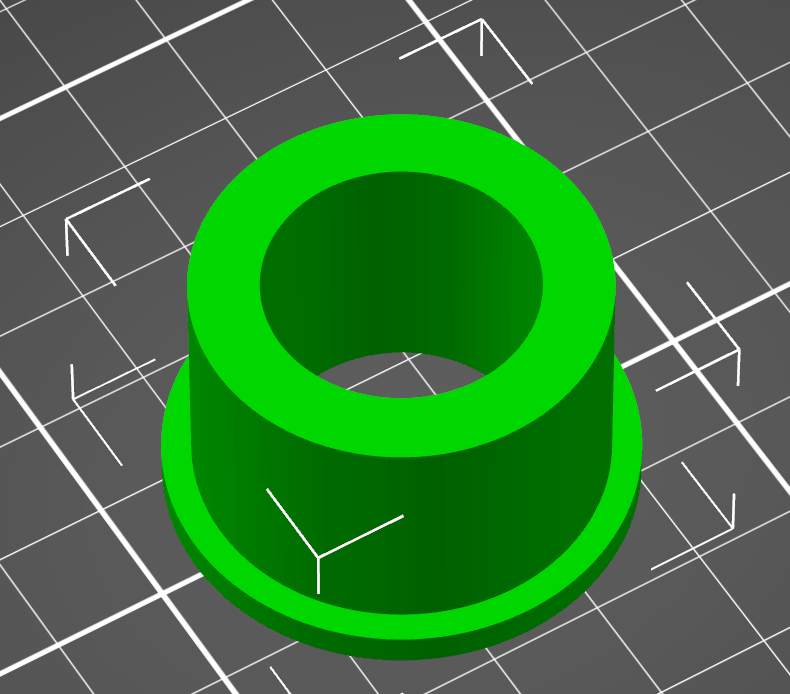
So finally I used the part as such and used split and transform to get the bottom part on the positive side of the top pane. and merged it with a solid part for the overhang. But resulting in something which does not have the exact measures as it should be (diameters + 2 mm).
If anyone knows the tricks to get what I exactly need, Please feel free to help.
Original tryout: https://cad.onshape.com/documents/c8ee4719c02d663805f16b9a/w/da98f870086e3bf7a35d11d6/e/fcd109ec545281764a9fef3a
Second tryout but with incorrect diameters:
May thanks in advance.
You seem to have found one of the rare few parts in the mcmaster carr catalog modeled with straight threads instead of the correct NPT geometry. CAD manager must have been asleep that day. I went and pulled one from the elbows catalogue which has better thread models I've validated with my own 3d prints. The way I approach models like this is to get a single studio cooked up with the features I want to use on other models and to use it as a seed for the Point Derive custom feature so if I need to make changes to my clearances or geometry for this 3/4" NPT geometry later I just need to update the source studio and it'll force downstream updates anywhere it's used. Think of it like a geometry catalog instead of a parts catalog.
Derek Van Allen | Engineering Consultant | MeddlerIt looks like you may have wanted the male version of that part so you can do a boolean subtract with an offset? If your going for perfection then you will probably just want to take that part and build yours around it with extrudes and such. no deleting faces needed.
Technically this would violate the specifications of NPT threads because you don't want the same clearances between the crown / root of the threads as you have between the thread faces, so you need to treat them with different offsets. That's why I copy the female thread, boolean to get the negative cavity of that (which is subtly different from the male thread) and then use that as my tool in another operation to create the female thread in a new location.
Derek Van Allen | Engineering Consultant | MeddlerYes that's what I was trying to say about perfection. But said it badly. ha. Depends on your needs… I took the mention of a slicer to mean its probably close enough with the right offset to be functional.
Many thanks Derek! Very clever idea this studio approach! I'm a newbie in modelling, so such kind of information means the world to me.
Tryng to use what you have done, fails because I have not the proper permissions (view only). I suppose that you have used your cutting tool (the NPT thread) to create the new model of the insert. I need to be able to export it to 3mf to 3D print it. Another question, for the NPT thread where did you put the largest diameter, on the top of the insert or on the bottom. The correct position is the bottom.
Once again, many thanks for all your help and information.
Grtz, Marc
I put the major diameter on top, but I went and updated it so it was on the bottom. Probably someone (not me, I've got too many other scripts on backburner to get to it) should make ThreadLab Pipe Thread Edition into a custom script so I don't need to find the correct McMaster Carr import to shove into models. Updated permissions to make that doc public so you can copy and play around with it.
Derek Van Allen | Engineering Consultant | Meddler