Welcome to the Onshape forum! Ask questions and join in the discussions about everything Onshape.
First time visiting? Here are some places to start:- Looking for a certain topic? Check out the categories filter or use Search (upper right).
- Need support? Ask a question to our Community Support category.
- Please submit support tickets for bugs but you can request improvements in the Product Feedback category.
- Be respectful, on topic and if you see a problem, Flag it.
If you would like to contact our Community Manager personally, feel free to send a private message or an email.
Sheetmetal Flange
 gordon_ross588
Member Posts: 6 ✭
gordon_ross588
Member Posts: 6 ✭
I am a Solid Edge user but have been migrating to Onshape over that last couple of months.
Loving Onshape but Solid Edge has a function called Contour flange that which sometimes is preferable to the Flange tool in Onshape.
Contour Flange in SE allows me to quickly turn this sketch:
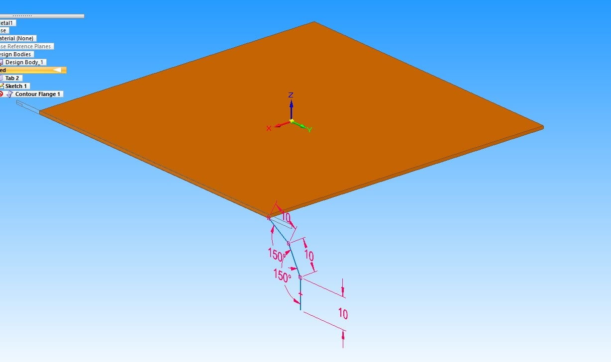
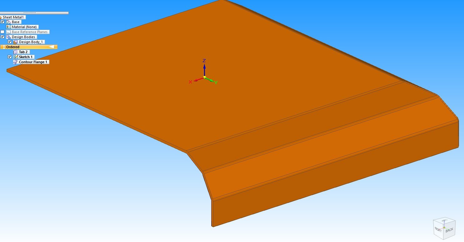
into this:
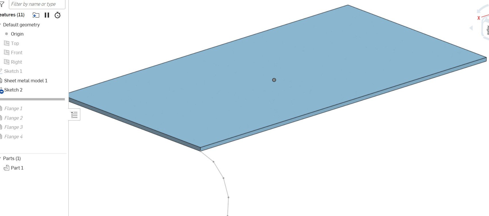
In Onshape I need to do something like this:
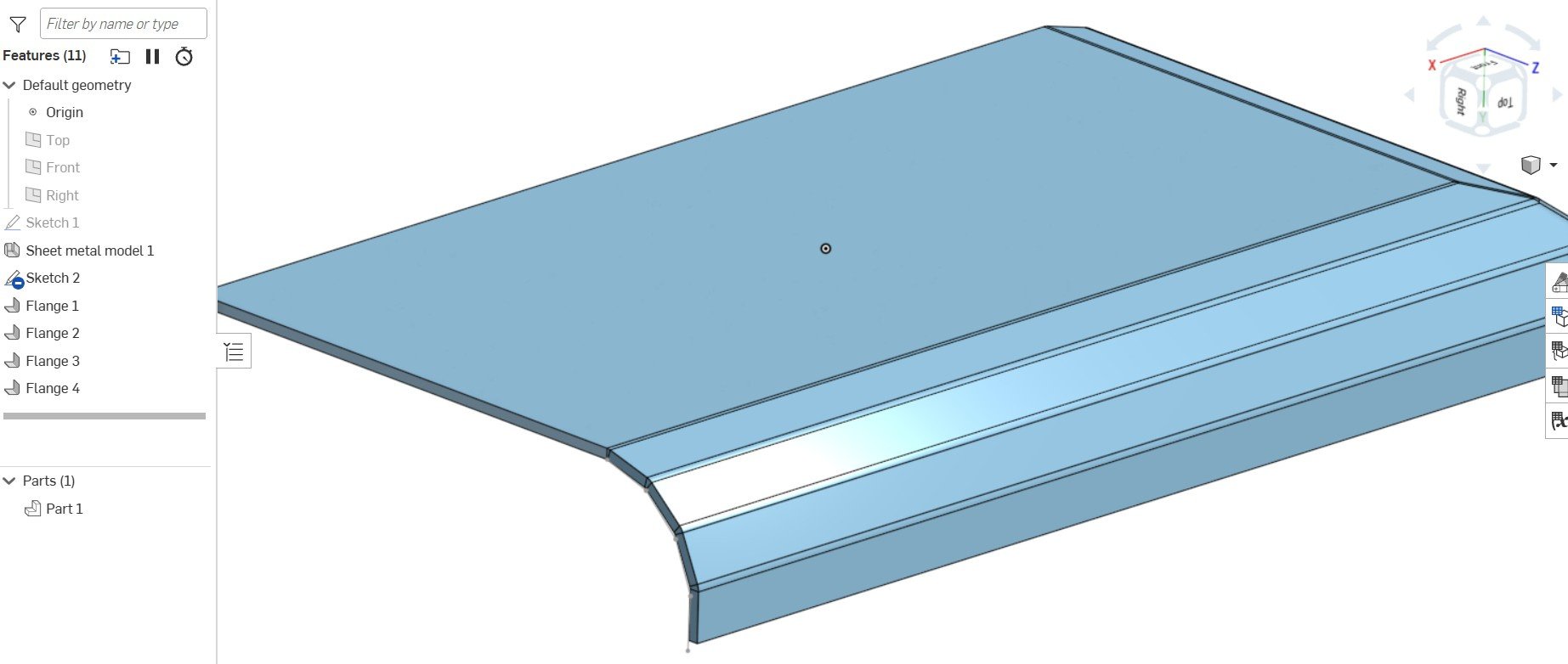
and build up the bends one at a time to look like this:
But that is cumbersome when I want to quickly convert sketch geometry into a few flanges.
My question is, is there another approach to this which I have missed?
Really like Onshape by the way.
And chapeau to whoever created the 'Shaped Flange' custom feature. I don't think I would be using Onshape without it.
Best Regards. Gordon
Answers
Have you tried modeling it first, then convert to sheet metal part?
Would love to have a contour flange feature in Onshape
Twitter: @BryanLAGdesign
Yes this tool would come in handy for sure…
I would have to go with what @martin_kopplow said: Onshape favors defining a solid first and using thicken/convert to create sheet metal.
I now start most sheet metal models with a solid shape, then convert and then add some flanges details as needed.
Here an example of how that works:
And this is taking it "to the extreme":
Hi Martin. Thanks for your help. I nearly always start my parts with a basic extrusion which I convert to SM. This work pretty well
But as the part evolves and it's necessary to add detail and flanges in my Solid Edge/Solid Works brain the contour flange would be useful.
To illustrate, this is the simple part where I started to scratch my head:
The part is basically converted to sheetmetal from a model. But I'm not sure I could have converted to curled bit on the RHS even if I had predicted it.
Thanks for the feedback. Gordon
Hello Martin. Thanks for the reply.
In general I start my parts with a converted model, like the simple part above. As the design evolves though it is necessary to add flanges and other details. It's the curled edge on the RHS when I started scratching my head. In my Solid Edge/Solidworks brain this is a very simple thing (as shown in original post). I have also tried to create another adjacent part and booleaning them together which works, but the result doesn't flatten successfully.
Thanks for your help.
This works as convert solid to sheet metal. This is robust enough to allow change depth of extrude or the initial length and width in sketch 1.
https://cad.onshape.com/documents/9a16e90e97ff0f49350854fe/w/8b1147e1bb96ce49e97d63d0/e/3e88da18014ccf9f76230d64
Thanks Eric