Welcome to the Onshape forum! Ask questions and join in the discussions about everything Onshape.
First time visiting? Here are some places to start:- Looking for a certain topic? Check out the categories filter or use Search (upper right).
- Need support? Ask a question to our Community Support category.
- Please submit support tickets for bugs but you can request improvements in the Product Feedback category.
- Be respectful, on topic and if you see a problem, Flag it.
If you would like to contact our Community Manager personally, feel free to send a private message or an email.
Critique my surface (because it worked by pure luck)
 hagus
Member Posts: 13 PRO
hagus
Member Posts: 13 PRO
I am slowly getting the hang of surfacing! Here is a recent success I wanted to share, in the hope someone can point out how it can be done more efficiently or using different techniques. Because I kinda feel like I just lucked out this time.
(note: I would be even more hopelessly lost without the inestimable Onsherpa, @EvanReese. His recent video on advanced surfacing was a gold mine of information! Strong recommend!)
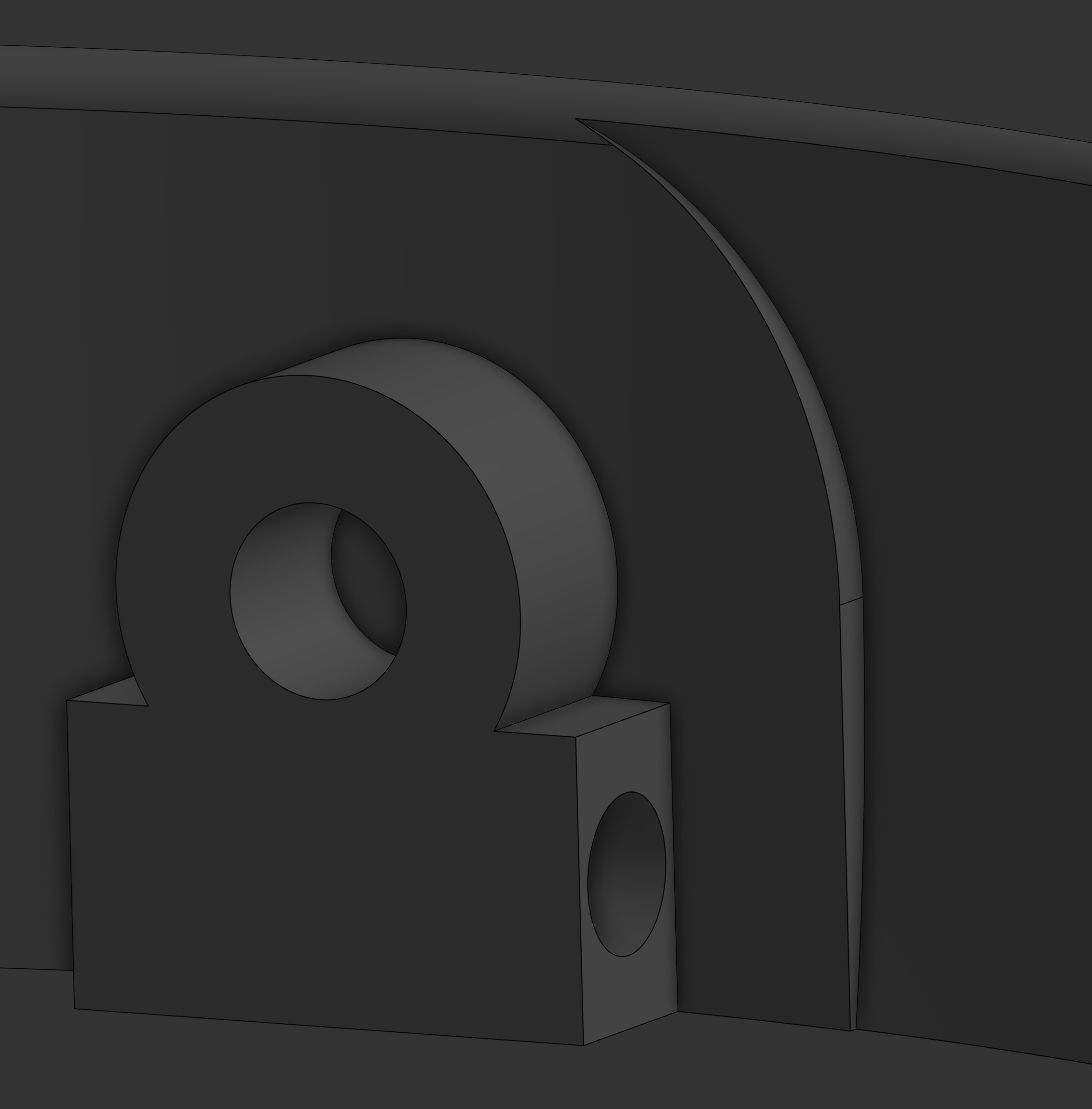
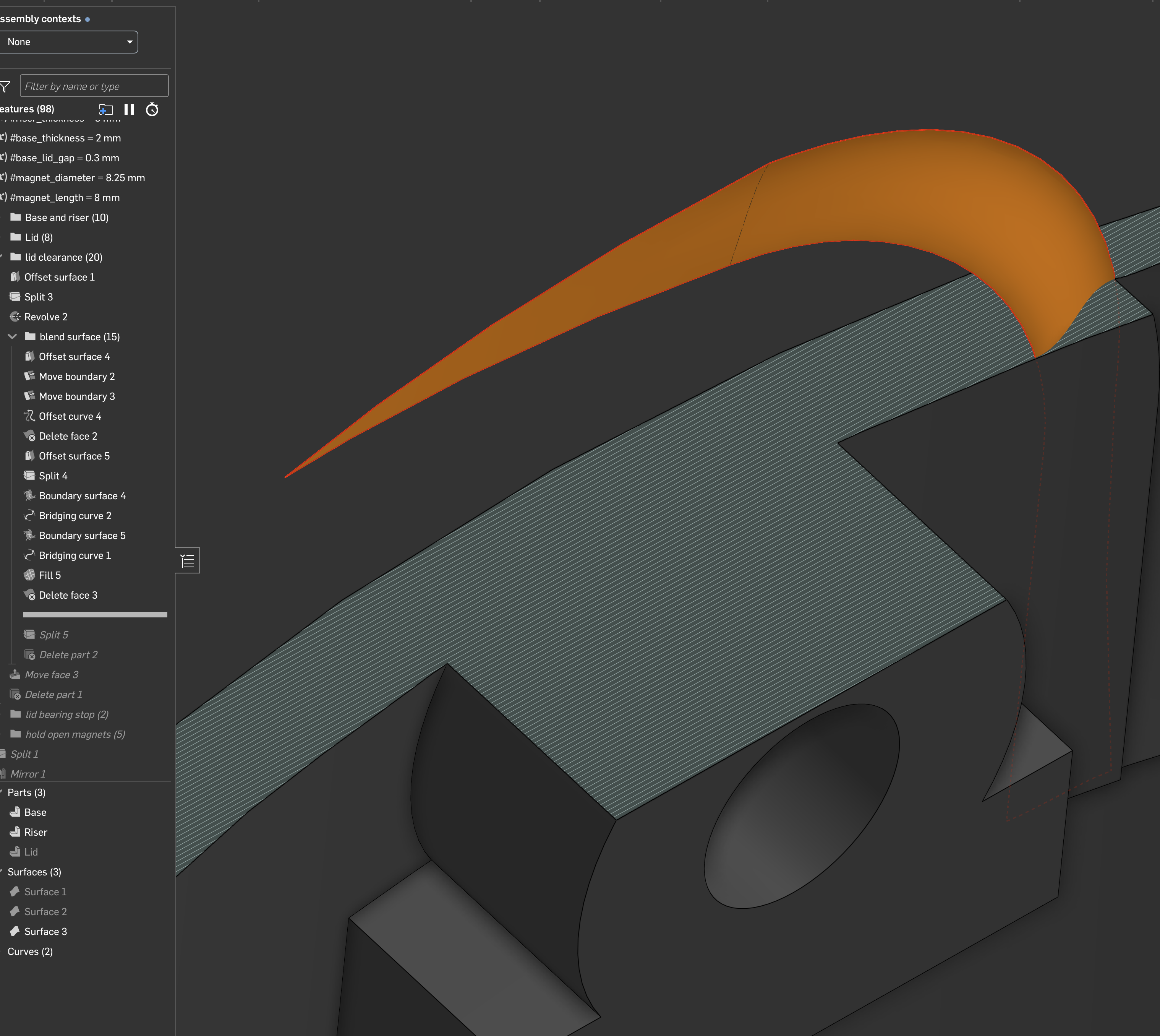
Recently I was modeling a household trash can, targeting FDM, and realized with the first prototype I didn't allow enough clearance for the lid to rotate. So I went back in and made some more aggressive cuts, which led to this fairly unsightly step in the model, which after some fussing around I managed to get blended in with tangent continuity.
Before | After |
|---|---|
|

|
I'm super curious to know how a professional user would tackle this problem. I seem to often hit cases like this, where I want to blend an edge down and need two surfaces rather than the single surface you can generate with a fillet or a face blend. The document is here and the folder with the specific steps is called "blend surfaces".
I think the core approach is probably standard: create surfaces for the start and end and bridge them with another face. What happens most of the time is that I end up trying random combinations of boundary surface and fills until one of them lets me pick "tangent" or better boundary conditions. Push buttons until angry red goes away.
Low quality surfaces | Profit! |
|---|---|

|
|
So some concrete questions:
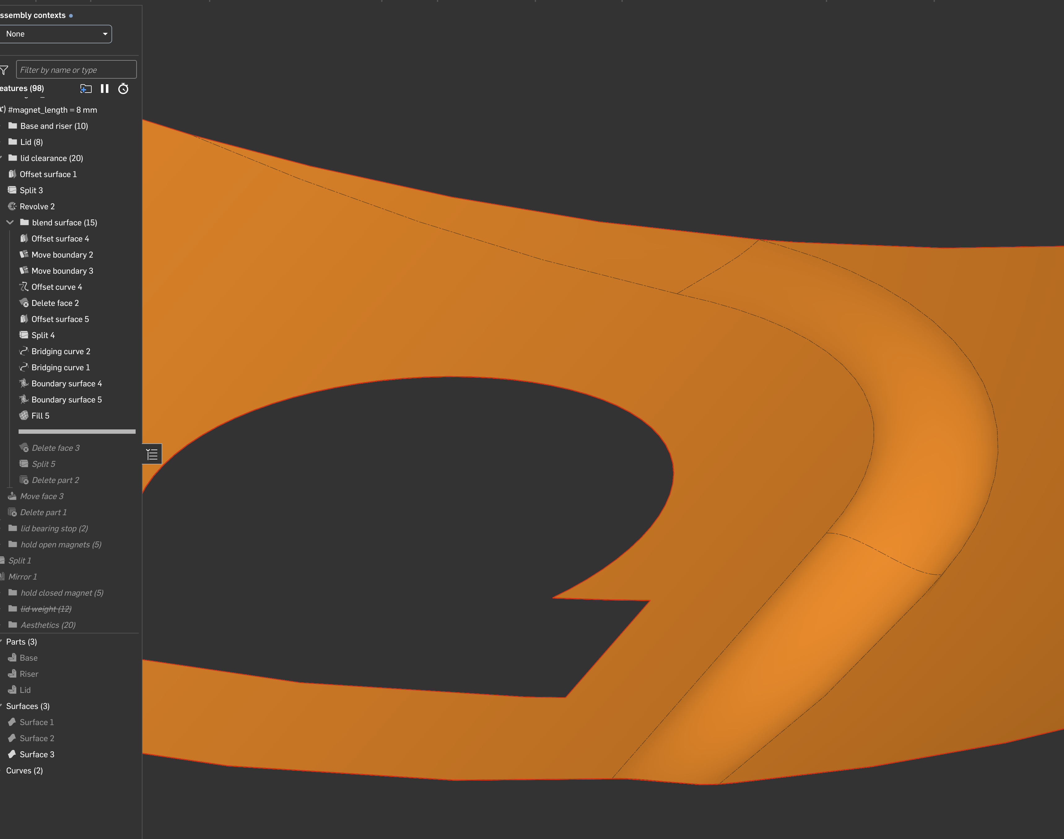
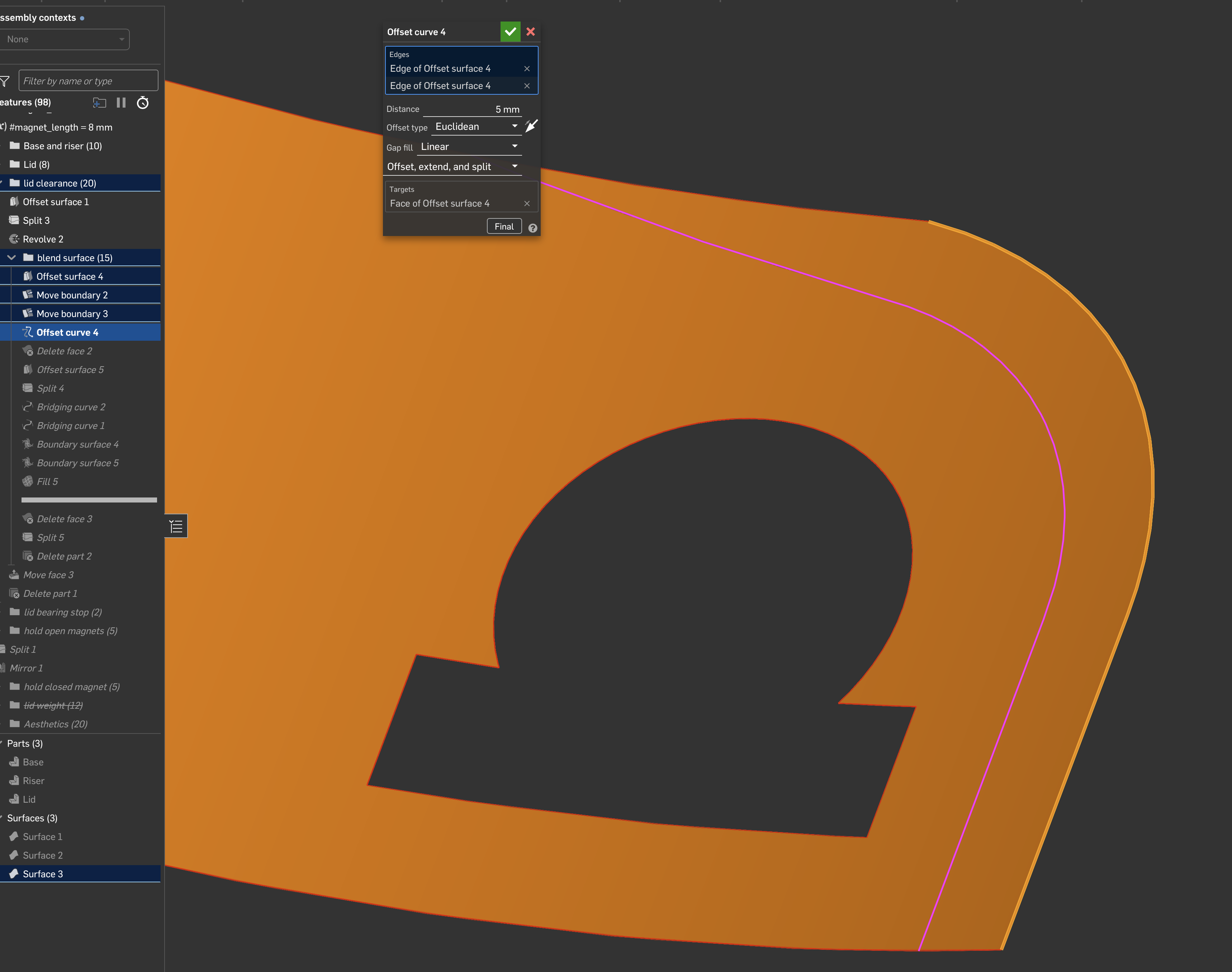
- Delineating the edges: I used offset curve because I heard projected curves tend to have a ton of control points that make things ugly. But how else might I have done it? I'm also a bit confused by projection direction, I seem to often struggle to get tangency after using one. I am dealing with a circular target, so what is the right direction? I already have an edge on the face I can use, so maybe offset curve was the right choice here?
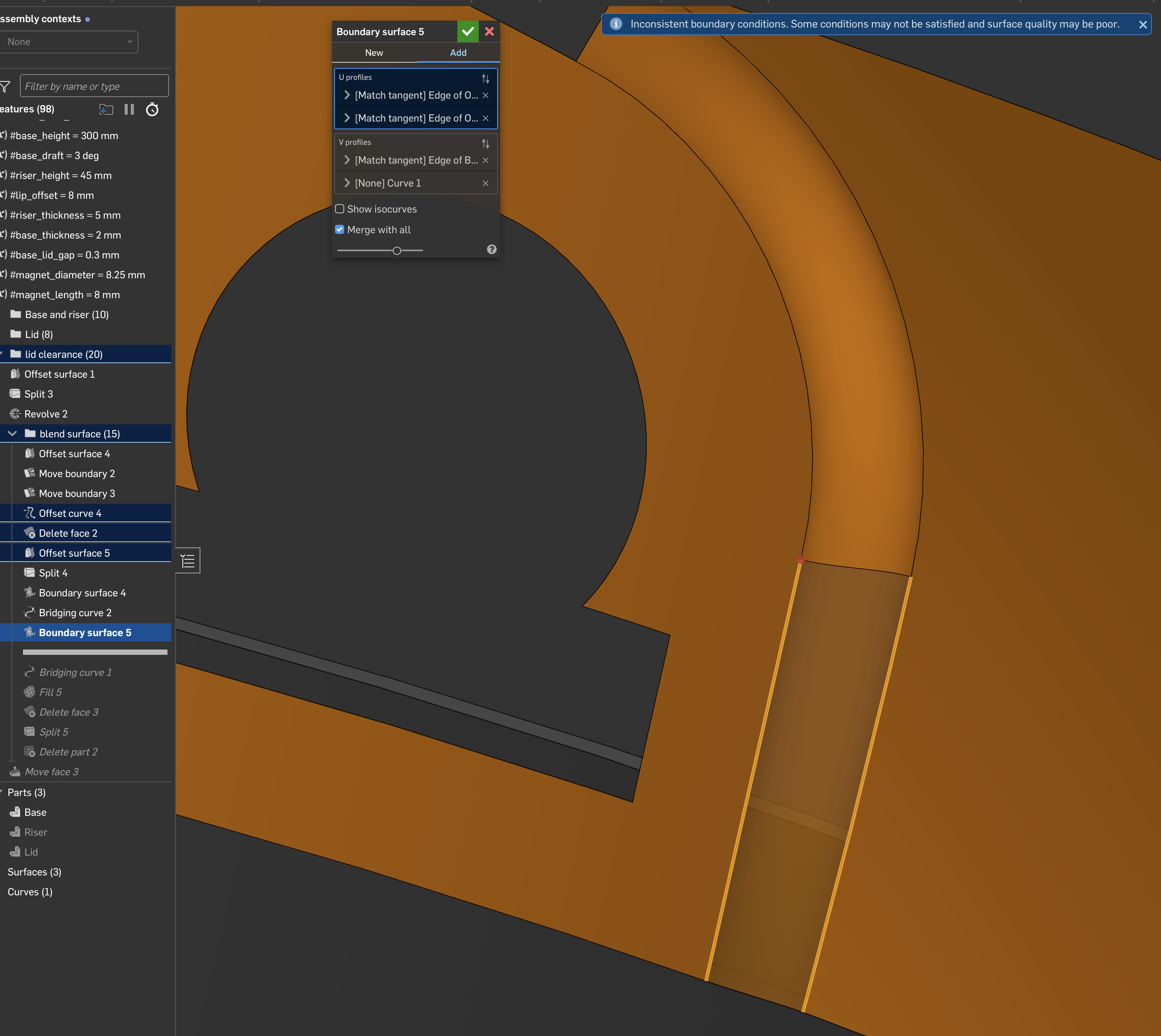
- Creating the surface: I could not get rid of the "inconsistent boundary conditions warning". Furthermore, I could not make the surface in one operation, I had to make each segment separately. These problems seem related but I couldn't figure out why.
- Using the surface: It felt a bit weird for "split" to work successfully as the final operation, i.e. I was able to split the target part with the surface I built, and it all worked out because the tangencies lined up, making it purely subtractive. See the picture below. However this wouldn't have been fun if my surface needed to add something to the part. What do you do then?
Before settling on splitting / deleting I messed around with replace face, as it occurred to me that felt pretty logical. Split the faces on the original part, then replace those with the surface. However, it complained withsurface to replace with needs to extend the size of faceswhich I confess to not really understanding what it's trying to tell me. So I'm still a bit lost on how to handle this as a general case.
I thought I might have to do: split the target, delete the target face, then enclose to get a part back. I am fairly sure (?) that would have worked, but I was rolled back in the feature tree and I knew that would blow away all references to the original part, so didn't want to try it unless I got stuck.
Thanks for any and all help!
Comments
Love that you're digging into surfacing! To be honest, this location on a product won't be seen, and it doesn't probably matter. Instead of surfacing this area, I'd probably just take the lid clearance face and continue it around the whole thing. But I still ended up getting sucked into it and made an impromptu video of my troubleshooting approach.
The Onsherpa | Reach peak Onshape productivity
www.theonsherpa.com
Thank you so much @EvanReese for taking the time to record this! Seeing experts work through the problem like this is incredibly valuable – if a bit nail biting when you're the author of the problem, lol.
Profile Sweeper – where has this been all my life? I will be using that a lot! The only critique I can offer the Great Onsherpa is that you crank out FeatureScript at such a velocity that it's hard to keep track (dear OnShape team: would be great if we could search by author so I could simply find all of Evan's published FS with a query …)
I definitely echo your thoughts on this being an unimportant piece of geometry to spend time yak shaving … the reality is that it's quite an old model, my partner was unsatisfied with the performance of the lid (in the assembly you can see how it rotates) and so I jumped into the middle of the tree and started making improvements in a bit of a rush. When revisiting old models I can't resist applying new tricks I've learned, and when I saw the revolve leave that cut I wanted to use it as an exercise for flexing my improved surfacing knowledge. But you hit almost every snag I saw, which is how this ended up as a question here. It's somewhat gratifying that it wasn't a straightforward fix!
I spend a lot of time printing weird things in polypropylene, so I would also echo that accommodations for FDM are impossible to avoid –– always be DFM'ing! I have more than one part studio with
nozzle_diameteras a variable. So I knew that crown on the top surface was going to be janky … but that too came about because I wasn't able to run a simple fillet or even chamfer around the top. Very likely those small artifacts getting in the way. Key lesson is definitely to roll back the tree and fix the root cause … in this case I had to resist the urge because I knew I'd redo the whole model from scratch if I started, and I'm not being paid to make trashcans ;) And I guess be vigilant for operations that leave little orphaned faces, probably a sign to stop and think.I was shocked when you deleted the face to reveal the degenerate looking geometry left behind from that revolve. That explains a lot! It must have been barely on the edge of self-intersecting. I didn't think much about it and assumed if it worked, it works. I wonder if there is a practice that can identify that, or some rule of thumb to learn? Something about off-axis revolves? Always check the curvature combs? I'm just somewhat surprised Onshape allowed it to be created in the first place.
I'll add also in reviewing the design I did all sorts of things I probably wouldn't do today. One of the very early extrudes has a draft angle. The first 20 features could be replaced with a sketch on the right plane and a revolve. So that all supports the lesson that the easiest way to avoid puzzlers like this is to not create the situation in the first place.
Again, appreciate the help immensely, and I hope all this is useful for other folks!
"a bit nail biting when you're the author of the problem." I mean you asked for feedback, haha, but for real I totally get it. I imagine almost any model (including mine) has things the author would do differently next time, so I doubt anyone will single you out for it. Heck, in the video I kept on basically saying "I'm doing it a bad way. Do as I say, not as I do."
I should add that I think the model looks pretty good. I may need to print one for my office. Happy printing!
The Onsherpa | Reach peak Onshape productivity
www.theonsherpa.com
Haha I definitely asked for it, but it's hard not have a little feeling of "oh no, I should have cleaned up my feature tree, it's all there on the screen! Oh god don't click on that one." I loved it!
I am not worried about being singled out, for the exact reason you're touching on: it's so important to air out mistakes, even if (especially if?) it induces a bit of cringe, which is quite natural. When I train or mentor people I very quickly get them normalized to that by inviting them to come and see every dumb mistake I make as soon as I make it.
We live in a world where almost every piece of research or forum answer or YouTube video or any didactic content appears to be a supercut reel of Awesome Wins That Were Obvious To Me At The Time. Discouraging for newcomers, it doesn't help them understand that it never gets any easier, it's always a struggle, because the moment you learn a thing you raise the bar and are back to not knowing. Even something as simple as "here is the crisp and clear answer; by the way it took me a full two hours to figure this out even though I've been doing this for 15 years" can work wonders.
You know, this makes me want a kind of TTT CAD challenge in slow-motion. Drop some near impossible problems on CAD experts so we can watch their process and see all the dead ends. I've seen some PCB design challenges that were a bit like that, and they're actually a lot of fun, probably some of the highest signal/noise content for me learning PCB design.
haha, well thanks for being a sport about it! I agree that watching troubleshooting can be as valuable as watching someone nail it.
The Onsherpa | Reach peak Onshape productivity
www.theonsherpa.com
I'm thinking of having the opposite challenge on the forum soon. I wanna do a CAD modeling challenge with a feature ban-list and see who can cook up the most disgusting feature tree to successfully solve a problem but using none of the intended methods. Best of the Worst type beat.
Derek Van Allen | Engineering Consultant | Meddler@Derek_Van_Allen_BD that would be amazing and I think instructive on multiple levels, haha. Occasionally I find myself doing that purely out of curiosity – can I do this without a sketch? Without any planes? It's amazing how far you can get with mate connectors and a misanthropic mindset! In programming there's a practice called "golfing", so named because you are scored on lines of code, and the fewest lines wins. The best entries resemble runes for opening a portal to hell, they are definitely not interpretable by mortals. Trying to golf your feature tree definitely produces some misbegotten results that would make for an interesting contest.
This might be too silly but how about: reconstruct Greg Brown's mag wheel demo using only tools from the Curve and Frame toolbars. Abuse of expression fields permitted but no FeatureScript. Hey you can do a lot of unwise things with Frame and Gusset, you just might have to dig around in public documents for a suitable sketch profile, lol.