Welcome to the Onshape forum! Ask questions and join in the discussions about everything Onshape.
First time visiting? Here are some places to start:- Looking for a certain topic? Check out the categories filter or use Search (upper right).
- Need support? Ask a question to our Community Support category.
- Please submit support tickets for bugs but you can request improvements in the Product Feedback category.
- Be respectful, on topic and if you see a problem, Flag it.
If you would like to contact our Community Manager personally, feel free to send a private message or an email.
How can I modify a flange so that the two side faces are aligned to parallel planes?
 jsejcksn
Member Posts: 13 ✭
jsejcksn
Member Posts: 13 ✭
Here's an image of the desired part geometry as a reference:
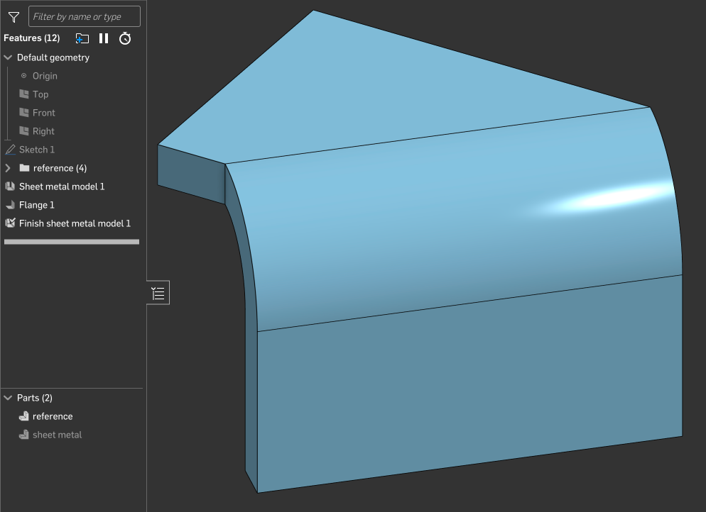
I would like to model this as a sheet metal part, but I'm not sure how to create identical geometry with the flange feature. Here are the existing flange feature details:
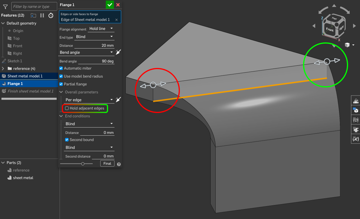
It appears that when deselecting "hold adjacent edges", the effect is only applied to the back edge and not the front edge. I would like for both side faces of the flange to be parallel and aligned to the implied perpendicular planes colocated at the ends of the flange edge. How can I modify the flange so that the resulting geometry is identical to the reference part geometry?
Here is a link to the example document:
Answers
I'm a bit confused. Looks to me that you already have what you're describing except that there is a non flat around the bend. That is the nature of sheet metal because of the normal cut used with most machines to be used. I have seen plasma torch set up with tilt head to cut counter sink on heavier material, but most not.https://cad.onshape.com/documents/7dce41e4fd270f1e6c28b5c0/w/74be216b7bf558a460f0ab0b/e/38e44e0536412f22b9c7ecb7
@glen_dewsbury I’m not sure which wording is confusing, but I would like to modify the flange so that the resulting geometry is identical to the reference part geometry — to end up with exactly the reference part geometry using only sheet metal features.
It does look like turning off the "hold adjacent edge" only "removes" material (i.e. doesn't add some to fill in the near corner). It looks like what you are looking for is a "bend ends normal to flange" or whatever you would call it….
While I don't see a way to do this in a single step, this is easily achieved using a "move face" feature:
@eric_pesty Thanks for the suggestion. The screenshot in your comment doesn't show all of the details of the move face feature operation (e.g. which face/faces were selected, etc.). Can you share a link to a public document with the feature applied? It would be ideal for the continuity of this thread if you can create a copy of the example document in my original message as the starting point.
@jsejcksn
What exactly defines sheet metal tools. The beauty of onshape is there is no changes to the studio or tool sets when creating sheet metal, the tools to create sheet metal just exist beside the rest.
For your part you can use Eric’s suggestion or create the part oversized and cut away the extra. Does the referenced part exist? you can use thicken face in sheet metal or you can get the same results by creating surfaces. There is probably dozens of ways to make this part, pick one an go.
So it turns out Onshape can be a bit weird with sheet metal corners… The method I showed works fine until about 30deg but doesn't behave properly at 45 where it does this:
The annoying thing is that it doesn't let you select the bend end face to move it after the fact. One workaround is to "reset" the corner by cutting it out like this:
Then you can select both the end of the flange and the bend and do the "move face":
It's a bit of a convoluted workaround, unfortunately we tend to run into these sort of situations once in a while with Onshape. Onshape is generally really predictable but sheet metal is the one area where strange things like this can happen. There's almost always a way to fix it but it can get annoying…
I'll submit a ticket as this kinda looks like a bug…
Here's the link to the document:
https://cad.onshape.com/documents/7be2b2937e5c1c5b8f0d6e22/w/4def68282a50bbb157d470fc/e/bac6b5ed2c69fdc088b95065
Sometimes what makes more sense to my brain is to build sheet metal models with surfaces or solids, and then convert to sheetmetal. Here's another way to get what you want with the flange.
https://cad.onshape.com/documents/295040ac1b60a6fc26138eb5/w/08d73507fa5106d8e0e2924b/e/2bedde1f3e8708cc50b6ae92
Simon Gatrall | Product Development, Engineering, Design, Onshape | Ex- IDEO, PCH, Unagi, Carbon | LinkedIn
How about select tangent propagation during the sheet metal translation to keep it the same as reference.
https://cad.onshape.com/documents/348d58de247234d86de95d49/w/72cce5692a0488547f1ffc13/e/04afa1d0aeb4195944d83a11
Twitter: @BryanLAGdesign
By the way, the move face option I showed is supposed to work for all angles, there is a bug report against it now…
@bryan_lagrange, I think the original question was about creating the geometry from "native" sheet metal tools. The "reference" was just an example of the desired end result.
Using convert or thicken is definitely a good approach but in this case the flange and move face should still be the "simplest" in terms of number steps. 1 sketch for the first face, sheet metal "thicken", flange feature, move face to align the "near" end.
Going back to the original question, this might actually be another bug as unchecking the "hold adjacent face" only seems to apply to the one end!
@eric_pesty Thanks for the link to the document — it helps clarify and I appreciate the demonstration of the move face technique applied to this scenario!
In addition to that workaround, I'm aware of others like the one mentioned by @wayne_sauder:
(as shown here in a branch in the example document) …but ultimately I'd like to avoid these kinds of "hacks" and stick with only sketches and features that convey design intent. I guess it seems like this is currently a limitation or bug in Onshape's sheet metal tools, based on what you said — thanks, again, for the research and reporting efforts.
@S1mon @bryan_lagrange Thank you for your suggestions to derive sheet metal from a solid model. While it would be straightforward to do with the part in the example document, that one is merely a minimal reproducible example for demonstration purposes in this discussion — the actual model that has this kind of feature is much more complex and not as practical to design using solid model tools.
Just a comment about "move face": it's been an integral part of Onshape sheet metal workflows from the start so I wouldn't label it as a "hack".
It took a bit of getting used to but when used with "up to" or variables and naming the features it can do a really good job capturing design intent.
It also works really well for things at odd angles in the "rotate" mode, especially when combined with mate connectors so it's worth including in your "standard" workflows.
I meant to add, the first three videos in this playlists are three different approaches to modelling the same part with some Onshape specific workflows…
https://www.youtube.com/watch?v=4MEKBsLa84U&list=PLa8CoVttf7wXTjnx5d_n87Qh-1kjymyIS
@eric_pesty Noted; thank you!