Welcome to the Onshape forum! Ask questions and join in the discussions about everything Onshape.
First time visiting? Here are some places to start:- Looking for a certain topic? Check out the categories filter or use Search (upper right).
- Need support? Ask a question to our Community Support category.
- Please submit support tickets for bugs but you can request improvements in the Product Feedback category.
- Be respectful, on topic and if you see a problem, Flag it.
If you would like to contact our Community Manager personally, feel free to send a private message or an email.
Can you add a point/vertex to an existing sketch? (Trying to fix a twisting loft)
 martin_brattensborg
Member Posts: 6 ✭
martin_brattensborg
Member Posts: 6 ✭
Hello everyone, I have what I assume to be a very beginner question that I think might have come up here before but that I was not able to get a definitive answer to this question.
In brief terms, I have drawn two sketches of two different trim profiles that I want to connect to a 3d mesh blending from one shape to the other. Based on my experiences with poly modeling for games and movies at work I assumed this meant using a loft (feel free to tell me if this is not the best solution/operation to achieve this when it comes to Onshape/CAD) but after doing so I've encountered the same issue that many, many others have which is twisting geometry, presumably due to the point/vertex count of the two sketches not matching up.
So, in that regards I would love to know if there is a way for me to enter my sketch and simply add another point or two to the sketch with the fewest points/verts to fix the twisting of the loft or if I am forced to actually redraw the whole sketch, keeping in mind how many points I put down as I trace a shape from an image to keep the point counts aligned between the two sketches.
I've tried to use the "Points" tool in the sketch to add more points but this does not seem to add points/verts the same as when using the line tool to initially draw the shape. I'm not sure if the point tool just adds free floating points that when added ontop of an existing line/edge gets constrained to it or what but when I try to move those points around after adding them it causes quite strange behavior where my points disconnect from the edge/line and the line and points start moving in different directions.
Here is a link to a version of the document:
https://cad.onshape.com/documents/1e45d15bbe404884b12fe271/v/597eb804d1815935e8b545d7/e/4e55fe0acd81514c0ebfd72b?renderMode=0&uiState=6963bd15565f42c8fb471bbf
As well as a simple screen shot of the twisting issue (though I assume this is probably nothing new):
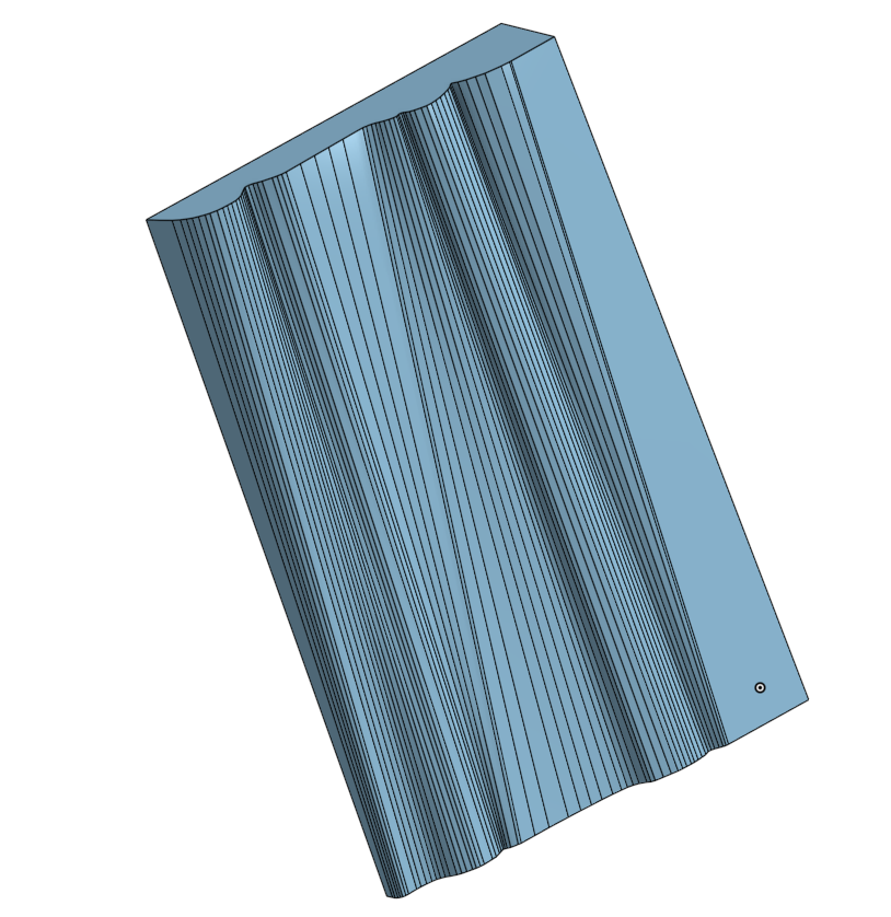
Thank you so much for the read!
Best Answers
-
 glen_dewsbury
Member Posts: 1,293 PRO
glen_dewsbury
Member Posts: 1,293 PRO
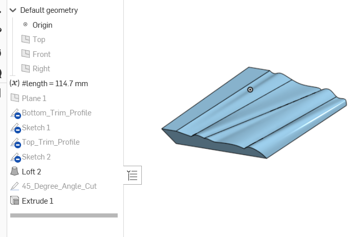
Looks like a lot of elements in the original end profiles. If this is wood trim it should be an extrude from only one profile. If it's been cut down at a an angle to match with a shorter trim on the next wall it should be cut in a straight line.
If your looking to translate from one trim to an other by 3D printing you'll have to play with the profile curves to make it look nice.
 1
1 -
 CADNurd
Member Posts: 86 ✭✭
CADNurd
Member Posts: 86 ✭✭
Splines! You need to learn how to trace over an image using 'Splines'. I had a look at your sketches and they appear to just be a long chain of straight line segments - which is why you have so many (too many) points to begin with.
Unemployed Onshaper - Operating on European time - More of me here ➤➤ https://linktr.ee/Liam.G
1
Answers
Looks like a lot of elements in the original end profiles. If this is wood trim it should be an extrude from only one profile. If it's been cut down at a an angle to match with a shorter trim on the next wall it should be cut in a straight line.
If your looking to translate from one trim to an other by 3D printing you'll have to play with the profile curves to make it look nice.
https://cad.onshape.com/documents/77abfa8f19fada471a3dd3b8/w/cc059759234d03ba99214a7e/e/4b3ca72865e11e44692d5399
Splines! You need to learn how to trace over an image using 'Splines'. I had a look at your sketches and they appear to just be a long chain of straight line segments - which is why you have so many (too many) points to begin with.
Unemployed Onshaper - Operating on European time - More of me here ➤➤ https://linktr.ee/Liam.G
Thanks for the reply and the edit/example!
You are correct in assuming this is meant for 3D printing. For some reason the people who owned my condo before me decided to use two different types of trim and instead of replacing the whole room I just wanted to make a transition piece between the two profiles for now.
I'm assuming when you mention there being too many elements you are talking about the fact that I used the line tool to create this instead of the spline tool? And based on the bezier style control points in your edit I am assuming that is what you used to make your example? (Just trying to understand for my own edification).
Yeah, I probably should learn about those. My first attempt was to use the splines but since I was having some issues making straight corners and other sharp angles without causing a lot of "automatic curvature" to come from the bezier interpolation I decided to try with the line tool instead which seemed to give more manual control.
I'll be sure to keep this in mind going forward that the spline tool is probably a better option and to look into how to make sharp angles with the spline tool instead of just falling back on trying to use the line tool.
Here's an idea that I think will look better than trying to match the trim so exactly. You can make a separate piece that would be similar to butting to a door jam. This could be around a corner or in a straight connection. Trim the new piece where ever you like to make it look pretty. It will separate the change in profile which looks better.
https://cad.onshape.com/documents/77abfa8f19fada471a3dd3b8/w/cc059759234d03ba99214a7e/e/8ac17ac981e64188d76defa3
An idea has occurred to me but since the corner in question is a very prevalent corner in my living room I'd like to try to make the fix as invisible as possible and I'm a bit afraid that a block solution like this will draw quite a bit of attention to itself.
This is definitely the backup plan if the transition pieces does not turn out alright though!
Yes, of course. Something like this to blend better.
https://cad.onshape.com/documents/77abfa8f19fada471a3dd3b8/w/cc059759234d03ba99214a7e/e/8ac17ac981e64188d76defa3