Welcome to the Onshape forum! Ask questions and join in the discussions about everything Onshape.
First time visiting? Here are some places to start:- Looking for a certain topic? Check out the categories filter or use Search (upper right).
- Need support? Ask a question to our Community Support category.
- Please submit support tickets for bugs but you can request improvements in the Product Feedback category.
- Be respectful, on topic and if you see a problem, Flag it.
If you would like to contact our Community Manager personally, feel free to send a private message or an email.
Custom Feature: Bip Joints - A Hand Bendable Sheet Metal Joint Feature
 Derek_Van_Allen_BD
Member Posts: 901 PRO
Derek_Van_Allen_BD
Member Posts: 901 PRO
If you're a producer of sheet metal parts, or design your parts for sheet metal production, there's a strong possibility that your manufacturing pipeline is catered towards hard flat flanges with edges parallel to the bends because that's what the manufacturing process favors. This manufacturing constraint is likely visible in the final design language of your parts. Now I love a clean press brake bend probably more than the next guy, but sometimes you just need to add a bend in a spot that would require a 4th dimensional press brake to press through the fabric of spacetime to achieve, and you just didn't quote the job like that. Maybe you don't have a press brake at all and you're working out of your garage. Behold: The Bip Joint.
Now, I'm not the first person to think about punching enough holes in sheet metal to be able to bend it by hand. Perforated bends are not a new concept to the world of manufacturing and I'm sure there are examples going back centuries of this in action. There are also already a handful of featurescripts that play with some variation of this kind of geometry, and my primary metal vendor OSHcut even lets you change a bend joint into a stitch cut geometry right in the online cart so your geometry can pass the manufacturing checks and you can get your stuff made without having to go back and add splits or change the flanges in a way that's more disruptive to certain CAD programs.
So why Bip Joints?
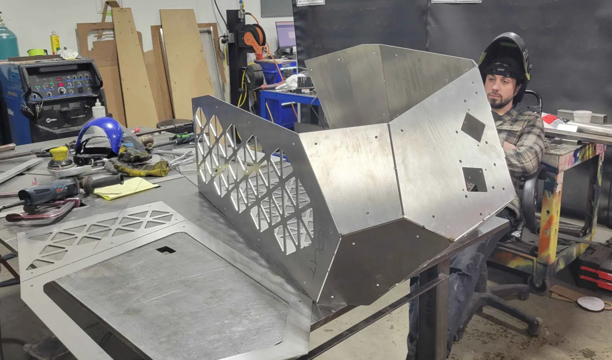
Because the panel gaps on this rock were enormous. I mean look at how unimpressed poor Liam is there. He's gotta fill all of those. The problem is almost all other solutions to this problem are optimized for ease of flat pattern cutting and bending or optimized of ease of drawing, but I need a solution that's optimized for weld filling and maintains tight gaps regardless of initial bend angle. We have another dozen of these that gotta get made and the development time of a script was easily less than the welding time of the whole job across 6 benches. So here's what sets Bip Joints apart from the rest in visual demonstration:
See how much tighter those gaps are between the panels? You'll save a fortune in filler metal using this script.
No... Why BIP Joints?
Oh. It's half bend half rip. It's a Bip. Look I said I wasn't the first to think of perforating metal, but as far as I can tell from my research I might be the first to alternate bend and rip geometry with their proper calculations in this manner and leverage the advantages of both so on the narrow chance I am actually the first to do this I call naming rights over the joint style.
Comments
Note for the early users of this script now that we're out of the main post: this first build was semi rushed for production of the job in the photo and I knowingly chose some ugly shortcuts in need of delivering something functional on time. So it's not as performant as can be and has a couple of bugs with flat pattern lines spawning in when you start with bends to convert to bips. Rips to bips seems to be working solid though and I wanted to get this out there for a little crowdsourcing review before polishing.
Derek Van Allen | Engineering Consultant | MeddlerThis is cool!
.
RENDERCAD
rendercad.ai - Photorealistic product rendering.
▚▞▚▞▚▞▚▞▚
________________________________________________________________________
Nice feature script
Twitter: @BryanLAGdesign
Oh and if you have access to a laser cutter or plasma table
cough@bryan_lagrangecoughand make something cool with this feature, please post pics of the final product and show me your builds. I'll be improving this script on my own over time but it's nice to have more data points to work from.Derek Van Allen | Engineering Consultant | MeddlerFor the curious: we've got some bips in the shop waiting for a free bench to get folded and filled.
I'll report back later with more progress photos and whether or not my low brow assumption of just drawing alternating bends and rips with existing kernel functions delivers weld gap perfection, but I just can't see how it wouldn't. Liam will let me know though. He's persnickety like that.
Derek Van Allen | Engineering Consultant | MeddlerLook forward to seeing the end result. Looks like the thickness of the material is about 10GA? What is the thickest material you have done this technique on?
Twitter: @BryanLAGdesign
11ga sheet actually, off by 1. This is just the first batch of things that came in so it will be the thickest by default when it gets bent up and we check how the gaps turn out but I ran some 1/2" plates through OSHcut's design checker to see what the extremes would look like, and it didn't freak out. Though after a certain point you should just switch to a tab and slot joint, which is what we're doing on other elements of the project that spawned this script but I would say anything 1/4" and under could be a viable Bip candidate.
Derek Van Allen | Engineering Consultant | Meddler