Welcome to the Onshape forum! Ask questions and join in the discussions about everything Onshape.
First time visiting? Here are some places to start:- Looking for a certain topic? Check out the categories filter or use Search (upper right).
- Need support? Ask a question to our Community Support category.
- Please submit support tickets for bugs but you can request improvements in the Product Feedback category.
- Be respectful, on topic and if you see a problem, Flag it.
If you would like to contact our Community Manager personally, feel free to send a private message or an email.
Configuration Hypothesis: When to Use Multiple Fixed Parts
 brandon_nichols678
Member Posts: 13 ✭✭
brandon_nichols678
Member Posts: 13 ✭✭
Wrestled with this one for more than a few hours, trying different approaches to obtain RH and LH versions of the simple assembly.
Like for example, duplicating the LH and rearranging parts to obtain the RH. All looked good, except the BOM did not roll up identical parts from different assemblies — and while I was able to configure my way out of that problem today, this does not bode well for BOM aggregation of many different subassemblies, all using a variable mix of the same identical bolts, washers and nuts. More on that later, if necessary…
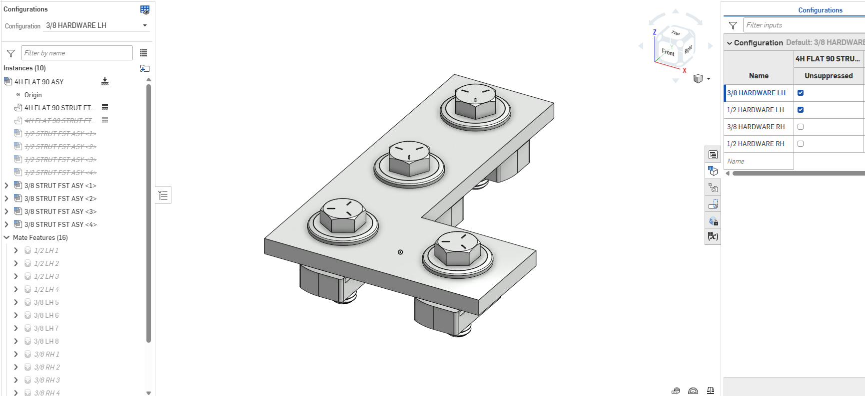
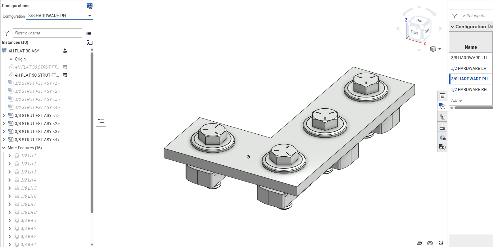
Back on topic, consider this 'Configuration Hypothesis': If an assembly's fixed part needs to move (in this case flip) for different configurations, then use another instance (also fixed) of the fixed part, and suppression toggles as needed in the configuration table. Net result being only one fixed part is active at a time.
Now perhaps this strategy is second nature to old OnShape hands, but as a newbie coming from Catia and SolidWorks, I cannot recall an assembly model I ever worked on in either of those environments that contained multiple fixed parts — that was a fundamental design no-no.
But at the very least in OnShape, the rule seems a bit more nuanced, allowing for multiple fixed parts so long as only one is active at a time per configuration.
See file STRUT KIT here. Side note: min-max limit positions used for angle and travel of strut nuts, with minimum 'usual' position, so 'reset' applied across all instances does a remarkable job. Approach seems to work satisfactorily in this application, since strut nut position is essentially cosmetic.
Any insights into…
• 'Configuration Hypothesis' or …
• Multiple fixed parts and the warning flag — can it be safely ignored? Or …
• More efficient OnShape configurations in general, or …
• Any way to drive multiple-selected limit positions to max or some arbitrary intermediate value, say with a Feature Script…
please advise!
Thanks in advance
Brandon W. Nichols, PE
Seattle, Washington
Comments
Sorry, I tried to understand your issue, but failed miserably. There should be no need for more than one fixed instance.
@NeilCooke yep, that's exactly what I thought for like 20 years.
Essential problem here is that if you need to configure a fixed (in this case asymmetric) part by moving it, the 'Fixed' feature breaks.
Solution is really elegantly simple: Make one fixed part instance per unique configuration position, all others suppressed.
In my example there are 4 configurations, but only 2 unique fixed part configuration positions.
If you Know A Better Way, I'm all ears — a working document would be helpful as an example!
Cheers!
Brandon W. Nichols, PE
Seattle, Washington
Not sure I fully understand but are you aware that you don't actually need any fixed parts? You can mate a part to the origin and configure the suppression (or orientation).
https://cad.onshape.com/documents/1567a13fd8e27e7eaae4c7c4/w/d886f0bafb1538346e73571a/e/e060993c724d52250e6db499?configuration=default&renderMode=0&tangentEdgeStyle=1&rightPanel=configPanel&uiState=69ae0e9779a22abdbc464b32
I wonder if the assembly mirror feature could help? If you set the mirror strategy to "derived" Onshape will create a new mirrored assembly you can use.
https://cad.onshape.com/documents/1567a13fd8e27e7eaae4c7c4/w/d886f0bafb1538346e73571a/e/a567d8a4e0a4e8b49ade5d6a?bomType=structured&renderMode=0&tangentEdgeStyle=1&rightPanel=BOMPanel&uiState=69ae0eb279a22abdbc464bbb
One fundamental issue here is that these two options are still going to be considered two different part numbers in a higher level as there is no "exclude from properties" option for assemblies (yet) (i.e. two different configuration of an assembly cannot be grouped as a single line in a BOM currently).
The only way to avoid this would be to not mate the fasteners in your sub assembly, sub-assemblies are always "flexible" by default so you can mate them at the the higher level. The performance penalty isn't anywhere as bad as "traditional" CAD, but it is more work…
https://cad.onshape.com/documents/1567a13fd8e27e7eaae4c7c4/w/d886f0bafb1538346e73571a/e/bc99d7d137a8d9245bfef272?bomType=structured&renderMode=0&tangentEdgeStyle=1&rightPanel=BOMPanel&uiState=69ae0ecf79a22abdbc464c05
There is one other thing I thought off (which doesn't solve grouping the LH and RH into a single top level BOM item) but makes for a simple structure:
You can abuse the "exclude from properties" of the part configuration and create a RH and LH configs of the bracket in a way the hole moves so that references don't break like this:
https://cad.onshape.com/documents/1567a13fd8e27e7eaae4c7c4/w/d886f0bafb1538346e73571a/e/aa3607c45cfe29892fcf9c49?configuration=default&renderMode=0&tangentEdgeStyle=1&rightPanel=configPanel&uiState=69ae13fe79a22abdbc465ea0
A couple general notes:
https://cad.onshape.com/documents/1af1d84667e6d56d56d2825d/w/d7ed219892d7ad119b22d9d6/e/713278bde91fd549bfac7a5b?configuration=List_XzwlOeLm5SzHs1%3D_1_2_00_00_00&renderMode=0&tangentEdgeStyle=1&rightPanel=configPanel&uiState=69ae19a33b18c46646ece597
Just realized I missed some stuff:
Look at the "named positions" for hardware height: you can lock a "flexible" subassembly to follow one of its named positions, which could help (or move it what you want and then "lock it".
You could also use a configuration variable but it will make the multiple top level BOM lines issue worse (different values of the config variable will be different BOM lines)
Also the position of the origin of a subassembly is essentially meaningless so you don't even really need to "fix" any of the parts, you could also just leave the bkt fixed an flip the fasteners, it just means it's "upside down" when you insert it in the assembly but it arguably shouldn't matter!
Also in the last example above with the linear pattern you can' adjust the nuts individually so maybe not what you need…
But you could do this instead:
https://cad.onshape.com/documents/1af1d84667e6d56d56d2825d/w/8dc08df07e712f46d551389e/e/713278bde91fd549bfac7a5b?configuration=List_XzwlOeLm5SzHs1%3D_3_8_HARDWARE_RH&renderMode=0&tangentEdgeStyle=1&rightPanel=configPanel&uiState=69ae23df3b18c46646ed1ef4
I also like splitting the configurations into multiple inputs as it makes things easier to maintain (no more duplicates values in the config columns). I believe this offers exactly the same function as your original assembly in a much cleaner package: