Welcome to the Onshape forum! Ask questions and join in the discussions about everything Onshape.
First time visiting? Here are some places to start:- Looking for a certain topic? Check out the categories filter or use Search (upper right).
- Need support? Ask a question to our Community Support category.
- Please submit support tickets for bugs but you can request improvements in the Product Feedback category.
- Be respectful, on topic and if you see a problem, Flag it.
If you would like to contact our Community Manager personally, feel free to send a private message or an email.
Having the legend "question" above the box where you want a title is .... not good.
Answers
-
Turns out I hadn't looked at your method/model in the right cross section:
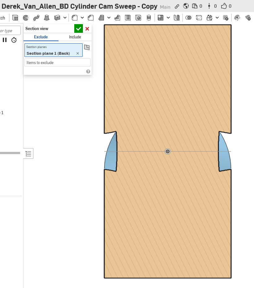
Those sloping faces of the slot are a problem.
Back to square one I think :(
0 -
Perfection is achievable.ill post it next week unless someone beats me to it.
0 -
It appears that way, but if you were to place a cylinder perpendicular to the inside of that slot surface and rock it around the slot profile that's the resultant angle from the sweeping cylinder. It doesn't seem like it should be intuitively but you need only look at the rest of this thread to see that sweeping body geometry is anything but intuitive. I'll try to set up an assembly cross section that shows a cylinder tool following those angles on those faces when I get a minute at my desk.
0 -
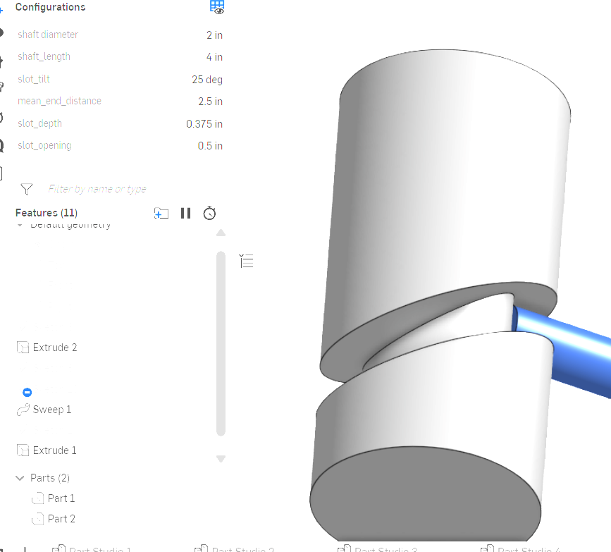
Here is a version using a sweep with a calculated path.
 0
0 -
Alright here's a few more section views and illustrations to hopefully elucidate the unintuitive cutting path this geometry takes:
Those wonky angles you see in the cross section across the side view? Those are supposed to be there for the pin to move through the slot. That's because we're not cutting a path relative to that cross section, this whole slot is cut on a 45 relative to that origin. If you look at the side view of where our cutter would engage with the side geometry, the cutter doesn't interact with those faces at the exact midpoint of the toolpath from that view. Those faces are getting cut at those points before or after the "midpoint" of the side view of the tool sweeping through.
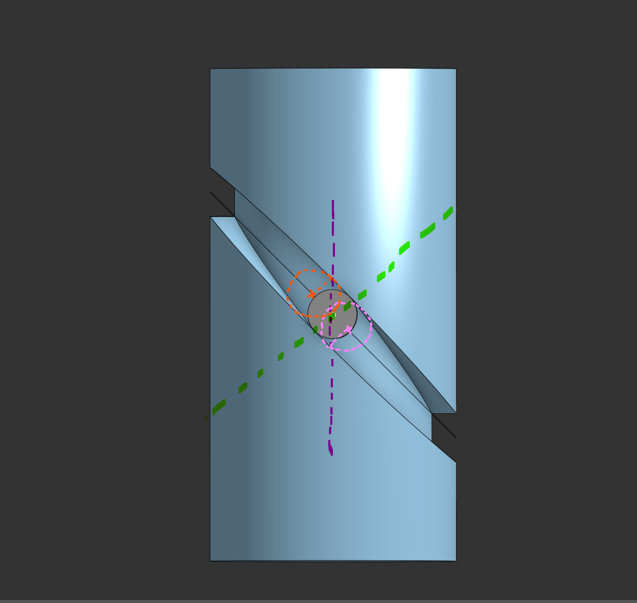
In this image the purple dotted line is your wonky section view where you see non-parallel cuts, and the adjustment I made in my gif above shows the true cutting dimension of the toolpath when positioned at that point in the green line as a cross section. You can see where the tool actually engages with the top face of the purple cross section drawn out in orange, and the bottom slot face drawn in pink. This is why you see those angled faces is because the cutter doesn't actually engage with those faces in the mid-plane of the part like you'd think it would. It happens both before and after the tool sweeps through the side plane.
@glen_dewsbury this example, too, falls prey to the minimum slot width constraint that the other sweep examples do because the sweep options don't allow you to specify both locked sweep direction and locked face orientation sufficient to keep the width consistent for this kind of manufacturing geometry,
1 -
You're right of course. Long, bad day, When I saw what looked like a problem, I just gave up in tired frustration.
In the cold light of the early hours of the morning a day later and yes. Looked at orthogonal to the relative direction of motion of the cam and follower, and its just fine: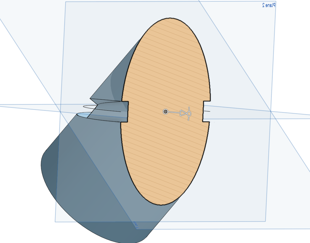 1
1 -
@Derek_Van_Allen_BD "this example, too, falls prey to the minimum slot width constraint that the other sweep examples do because the sweep options don't allow you to specify both locked sweep direction and locked face orientation sufficient to keep the width consistent for this kind of manufacturing geometry,"
This part is destined to be 3D printed (mSLA), at least in the first instance, so toolpaths are not a thing. If the overall design works out to the point I want a metal version, I wouold use lost polymer investment casting (ala:https://www.youtube.com/watch?v=lJ4qE95lAXs) )
If it were ever to be manufactured at scale, MIM would be my first choice. The g-code required to generate this profile accurately would be a nightmare. Close to hypoid gear level of complexity.
The only way I've come close to a "totally accurate" model is to forgoe the builtin tools and resort to old fashioned methods: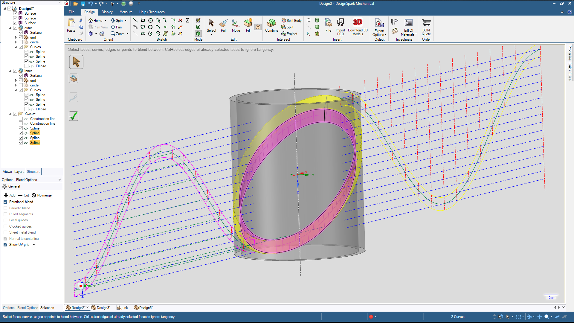
This involves projecting the ellipses (from both outer and inner cylindrical surfaces) onto 2D maps, constructing offsets normal to the projected ellipse (sinewave) at each point, and projecting the ends of those points back to 3D.
Which is incredibly tedious, time consuming and error prone, though much less so with electronic help. There's also the problem that whilst your caught up in the minutiae of all the 2D and 3D projections involved; its easy to miss a (glaring above) macroscopic mistake that renders it all nearly wasted. (I mentioned a long, bad day!).
I've no idea if this is even possible with OS given you cannot easily reference existing geometry from within a sketch, nor (based on my knowledge so far!) construct curves directly in 3D.
Perhaps constructing the maps for both inner and outer cylinders, wrapping the around their respective cylinders and the blending between the resulting curves might be possible. I did look, but do not yet see the method for the latter step.
Anyway, thankyou greatly for your insights in this.0 -
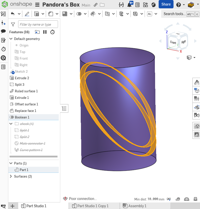
Alright @buk_browseruk here is your perfect slot request 10mm wide by 5mm deep all the way around (according to the onshape measure tool) Now all the way up to 8 features. Link below.
0 -
Bringing some more analysis tools to the table to inspect these surfaces shows that your slot width varies from 10mm thick to 10.032mm, which is pretty good. A 10mm pin will definitely not get stuck in the slot.
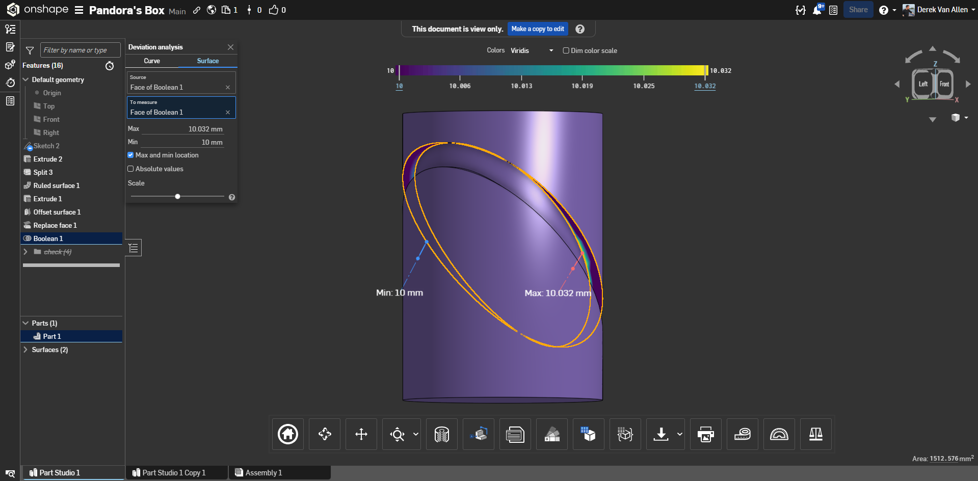
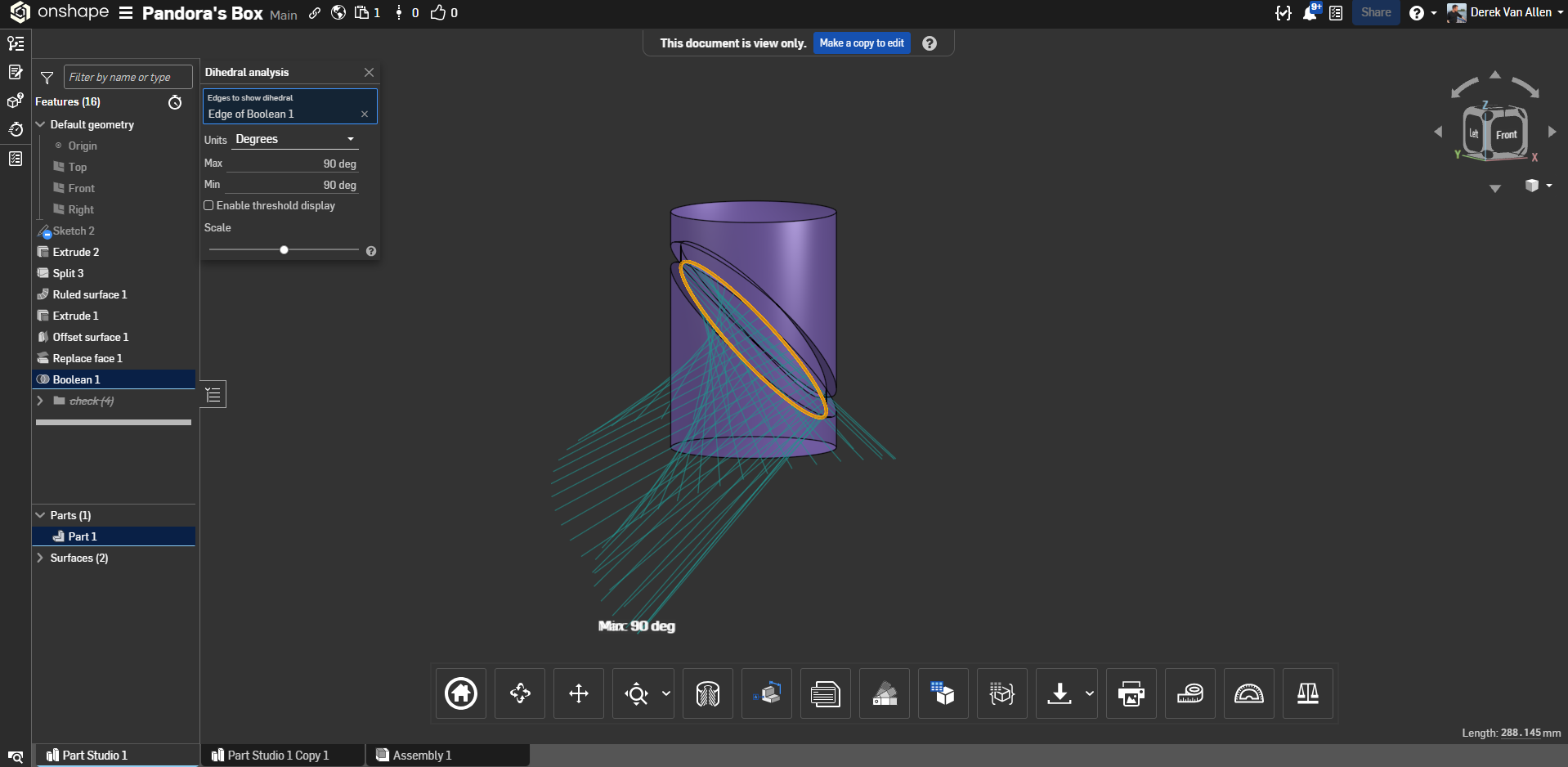
The inside edge of the bottom face of the slot also has a perfect dihedral angle as well:
The top edge of that slot, however, has an almost 10 degree deviation in angle across its geometry.
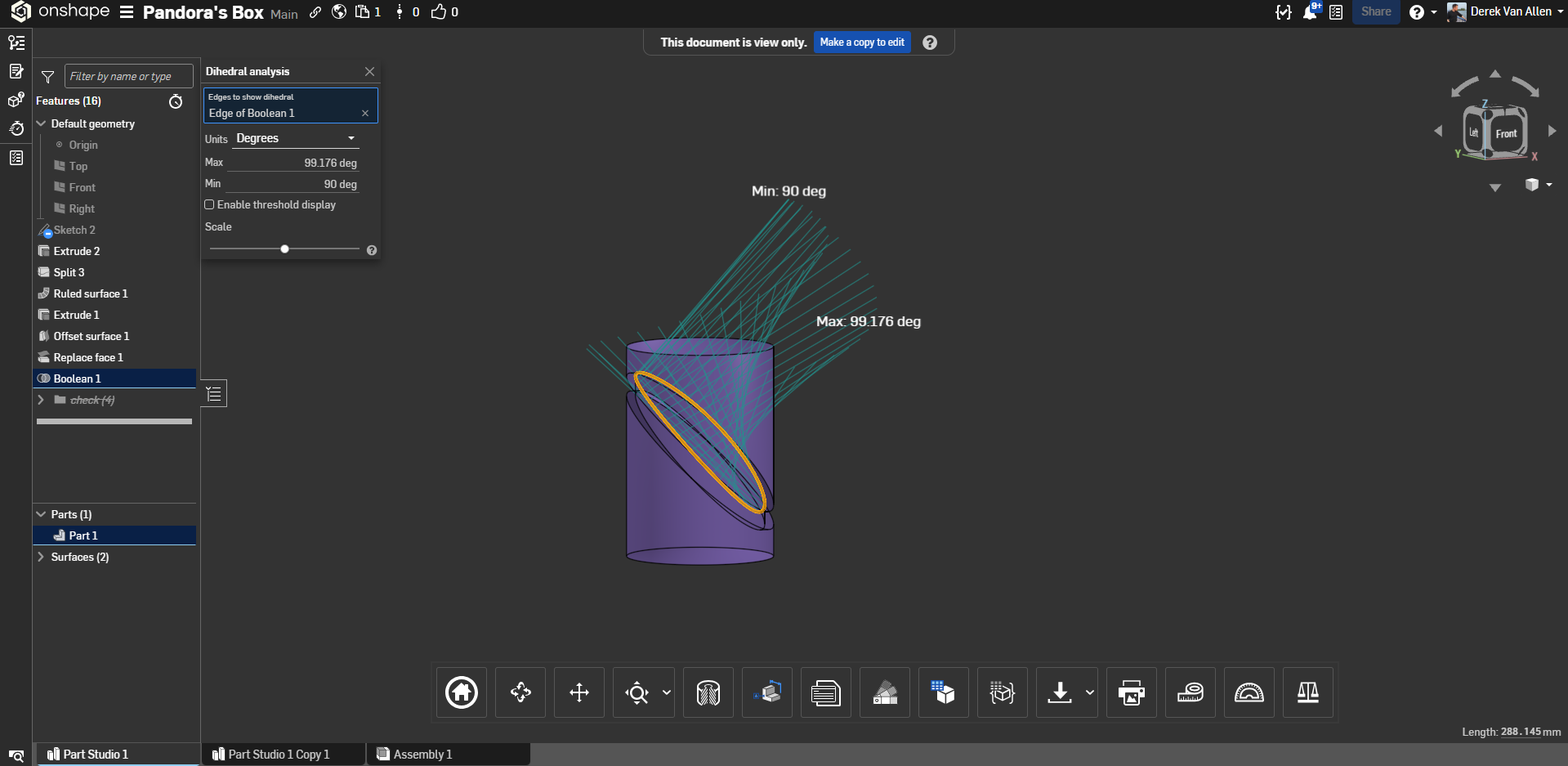
So although the bottom of the slot might claim a label of perfection, the top side of it appears not to be an entirely perfect match for it.
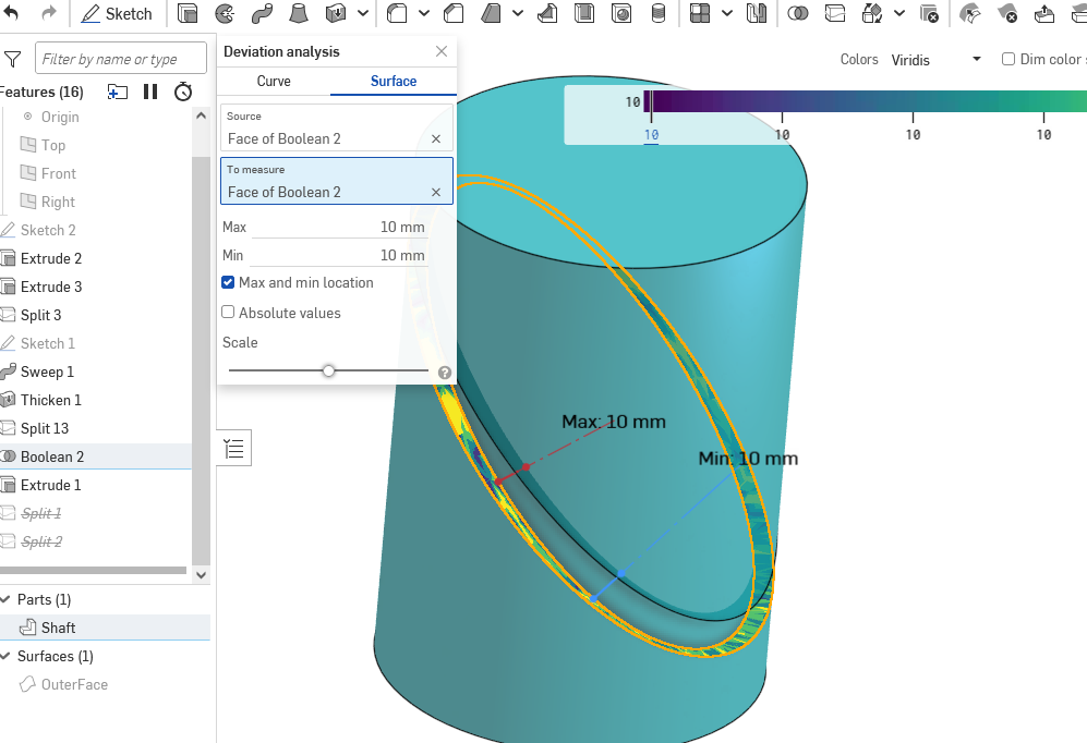
In my example with the ruled surface thickened from the middle out we see 10mm max and min dimension via surface deviation inspection:
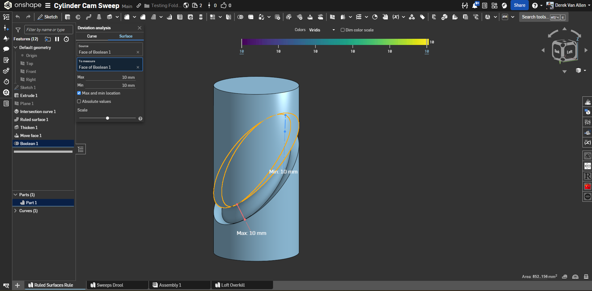
And dihedrals that are +- .002 degrees at the root of my slot geometry.
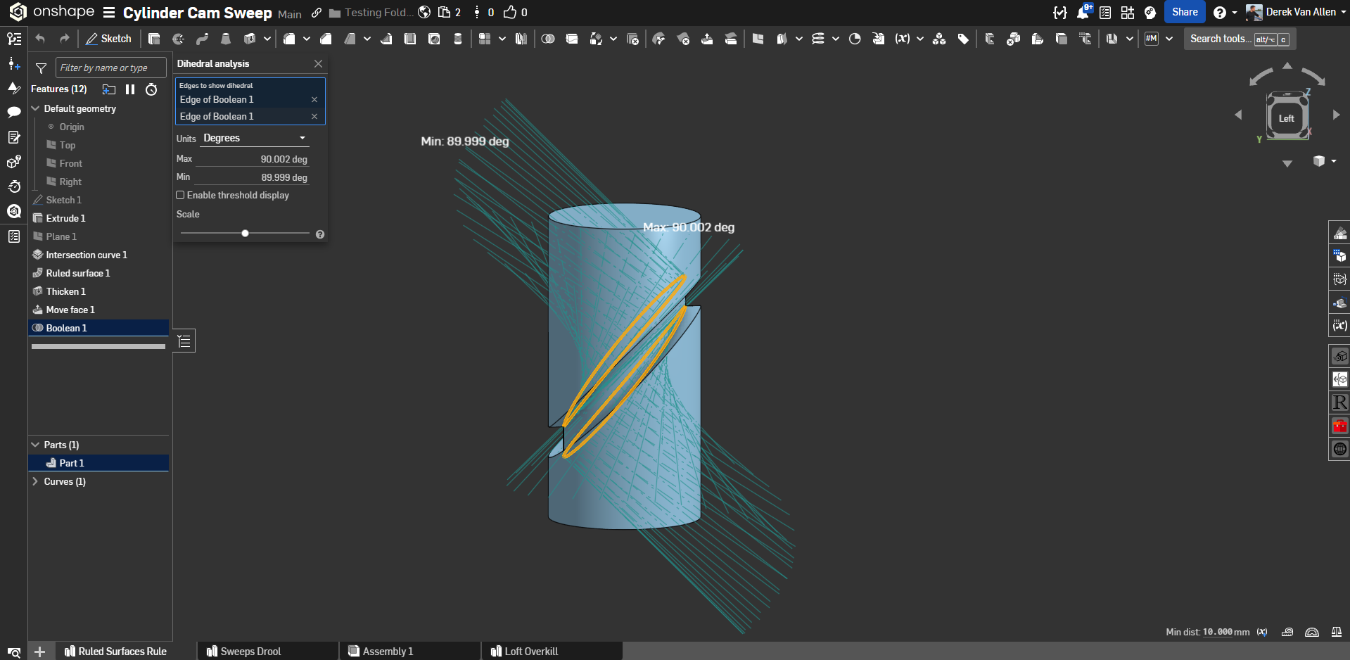
And I'm not entirely sure that the dihedral analysis tool is fully capable of analyzing these surface conditions entirely accurately to that level of precision, but given that my slot is generated via ruled surface it would not surprise me if this angular deviance is a result of the approximation routines that feature runs.
0 -
Well done Derek. Interesting that Onshape is introducing deviations like that despite best efforts to avoid them. I've spent enough energy messing with this to know I've learned a thing or two. Interesting stuff… I've played with my method a bit more and it seems anytime I go from the ruled surface to a solid geometry,,,onshape is introducing a deviation. I might play around more to see what else I can learn.
0 -
I'll also add to this discussion, I am completely ignoring what happens with the face at the center of the slot profile that corresponds to the bottom of the end mill that would be making this cut. What I would need to do to properly capture the bottom of the cut would be to sweep the bottom circular face of a cutter along the path and main the angular constraints I previously described along the whole toolpath, but that will almost always result in self intersection of sweep path with those high-angle-of-attack faces. That's one of the things keeping Body Sweep features from being easier to implement.
Also anyone using this kind of modeling practice for cam generation isn't riding that face of the part for their cam action anyway. So you can ignore how incorrect it is because it won't matter at the CNC.
2 -
Thanks Mdesign. That downloads via STEP and is true to < 5nm, so good enough.
Like, Derek Van Allen, I performed some analysis on the results: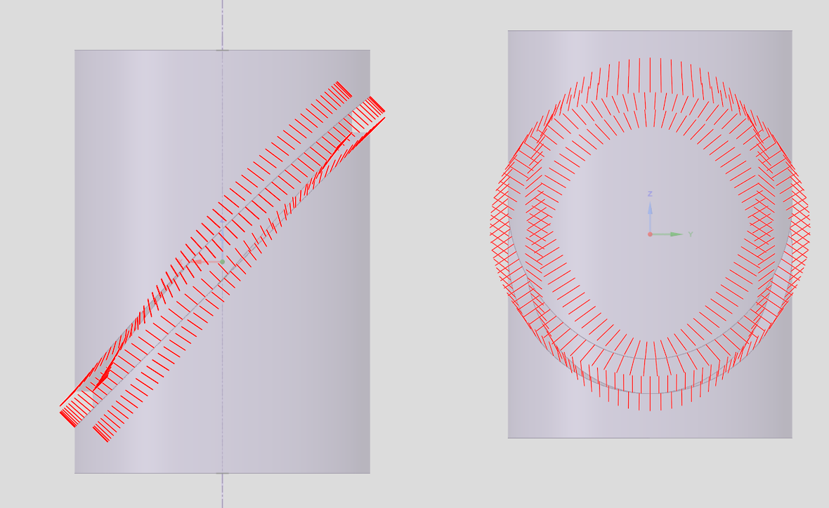
One interesting point is the process you use produces an asymmetric groove:
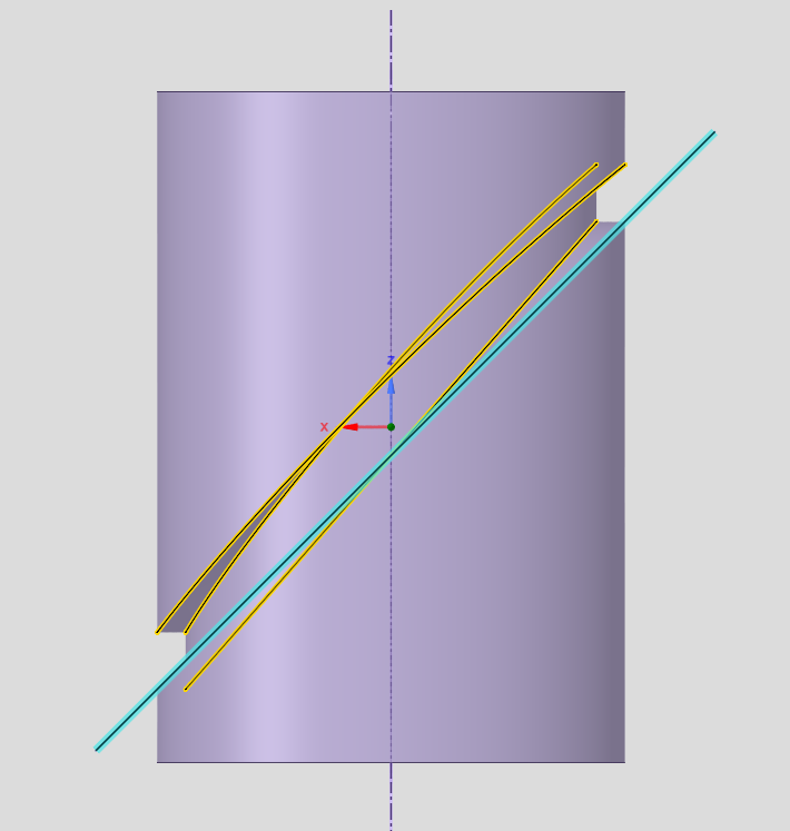
You an see that the outer edge of the bottom face of the grrove, is on a plane and the inner edge almost so, but the upper face of the groove has both edges bowed distinctly upwards in the middle.
A symmetrical groove would ensure than the linear motion of the follower would have consistent acceleration profiles in both directions. The differences are small, but show up down stream.
For me, the most important thing is trying to understand how your process works, and I'm struggling.
You create the elliptical split: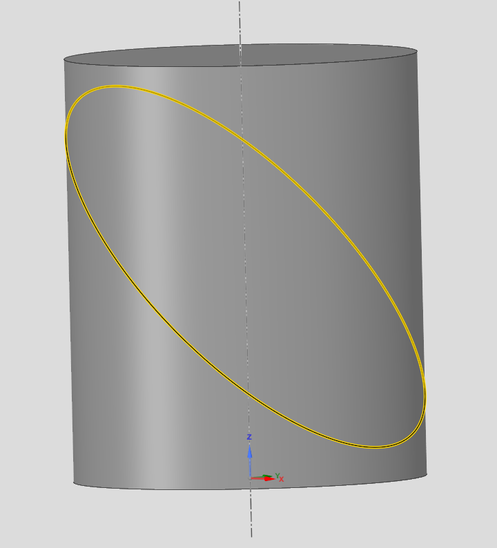
You create the 'normal' type Ruled surface, with a 10mm offset (rather than 5mm required radial depth), which may or may not be significant.

You then do a (mysterious) (new, thin) extrude of the top edge of the cylinder, that during operation produces a second solid (something like this):
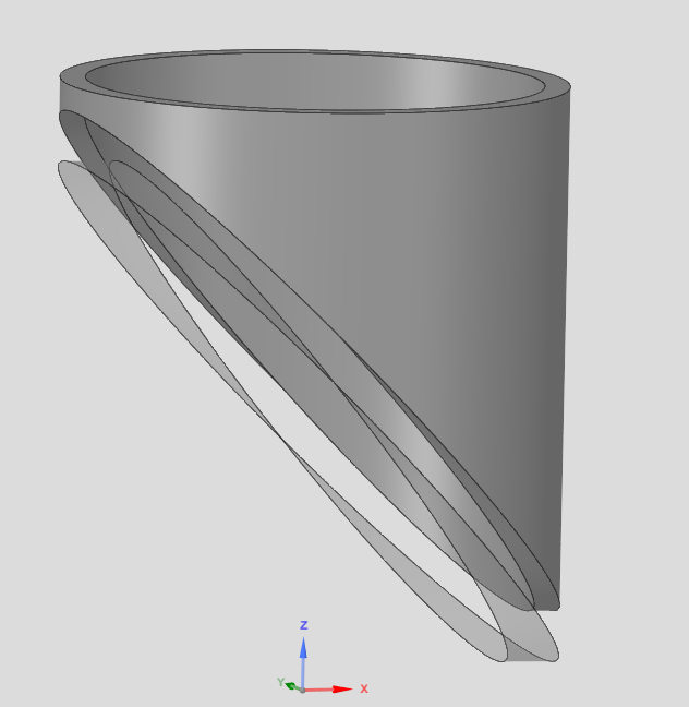
But when the operation is complete, the solid disappears (thin! with thickness 0), and a second surface — the bottom face of that temporary solid — appears in the parts list:
This (visually) looks like a complicated way to duplicate the existing surface, offset 10mm above the existing one, whilst reducing its axial width to 5mm; but is obviously more than that as simply offsetting the existing surface 10mm leaves a minimal gap of 6.something mm: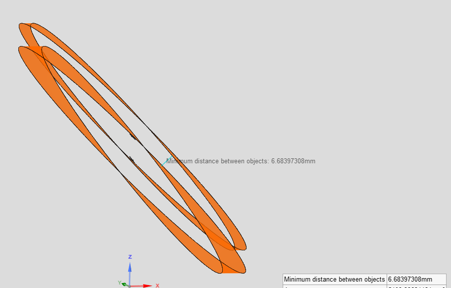
Besides, the next operation is an offset surface of surface 1, not the new surface, by 10mm. However, during this operation the mysteriously vanishing part 2 reappears (temporarally) in the parts list, despite that surface 1 is referenced (not surface 2 that was derived from it!?)
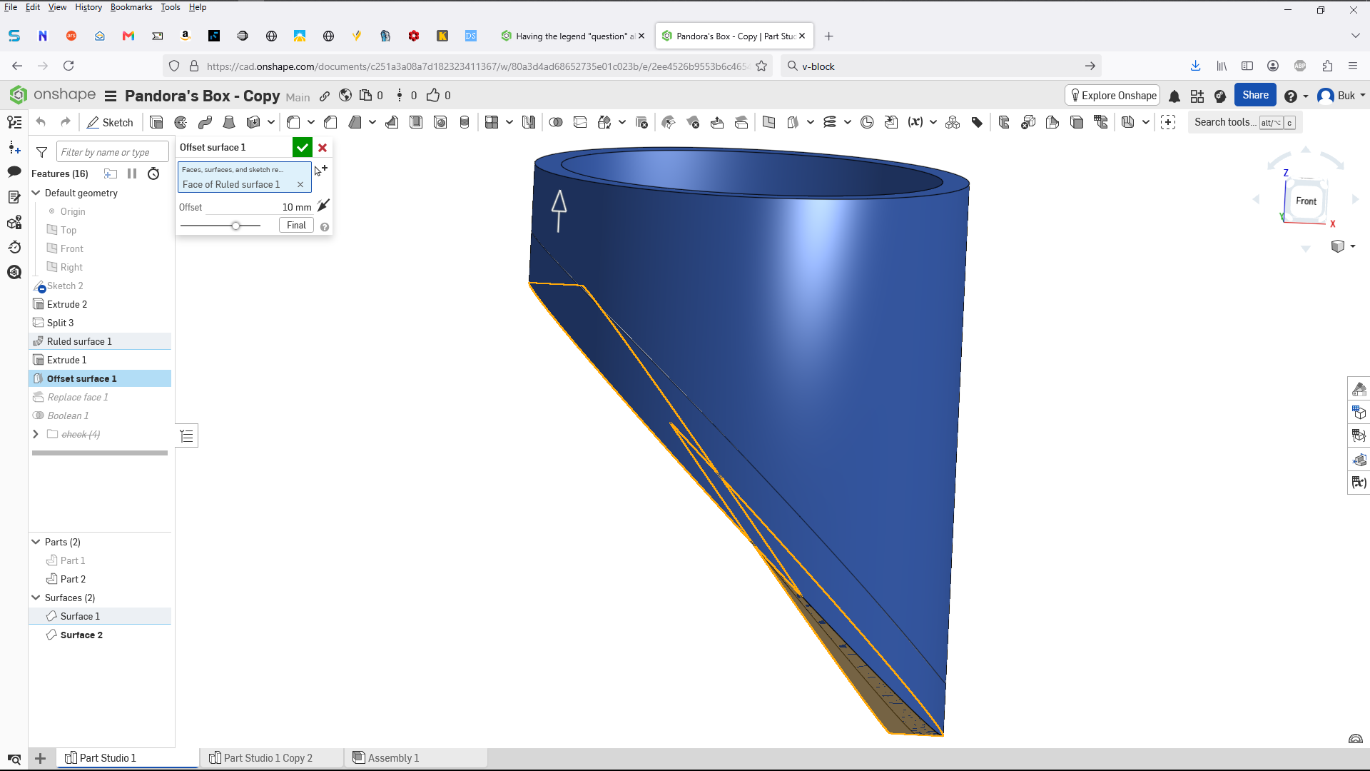
(No attempt to re-create this as I have no idea what is going on at this point. :( )
At this point you do a Replace face. Which is a clear operation that in SC terms is a "Pull face upto face". I can easily replicate the example of Replace face shown in https://cad.onshape.com/help/Content/PartStudio/replace_face.htm#Examples: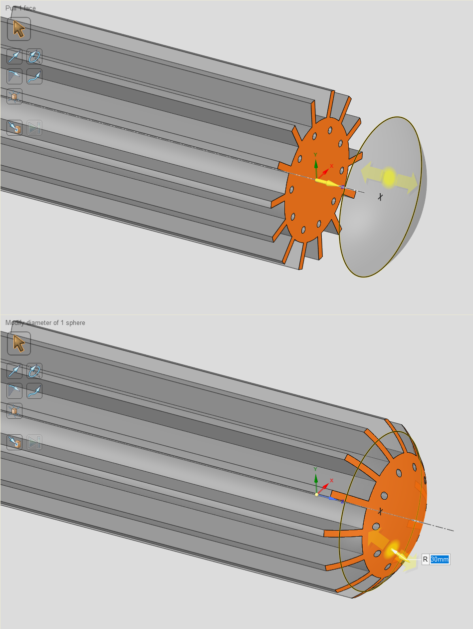
But applying that understanding to the operation you perform, in the absence of understanding the preceding operation, leaves me cold.
Once again the transient part 2 reappears during this operation, despite that none of the elements that created it — sketch 2, extrude 2 nor surface 2 — are referenced in this Replace Face.
Utterly befuddled is the best way of describing my mood.
And FYI (listening @jim_zamecnik?) I'm still being subject to a 'newbie approval delay' that appears to time out at the next midnight GMT, as best as I can discern. Probably as a result of the downvotes I got from Beavis & Butthead.
So if my responses to your sterling work seem lackadasical, its not for want of enthusiasm.
I'm really trying to get to grips with OS — by relating its operations back to those I understand — and I would really like to be able to print a good version of the cam. The existing one was made to work by crudely offsetting one face to achieve a 10mm minimum, but that introduces a considerable amount of slop.-1 -
Wow, You put a lot of time in that response. I've been entertained by the exercise but have spent way more time than I probably should have on it. I was generally curious as to what I would learn through the process.
The thin extrude was simply an attempt to control the depth better than the prior attempt( which fixed the width of the slot but then exposed the depth changing). Nothing disappears when that is created as far as I can see. I'm simply trying to create an accurate slot that is solid which is subtracted from the main body.
I hadn't noticed the asymmetry but suspected that would be the case probably with what I was doing (I was just trying to save effort with less features and still meet your dimensional requirements), Thanks for pointing that out. That most certainly is due to the nature of not using a center slot control feature. I simply offset the full 10mm instead of 5 each way.
The ruled surface not being 5mm is insignificant as its only used to control other geometry. Sometimes it helps to have controlling geometry overlap a bit to prevent some issues.
The replace face is simply easier to do that a split which is why I chose to use that.
After Derek's deviation post it looks like an impossible moving target of a goal which is kinda funny considering the path and length of this thread so far. Plus I've run into some odd results using the surface deviation tools that would make it impossible to validate with much more accurately than what Derek has shown. I'll probably spend a few more minutes with it but I may have to move on to more productive things soon. We may have to settle for good enough. If I get much further down the rabbit hole I may not be able to get back out.
0 -
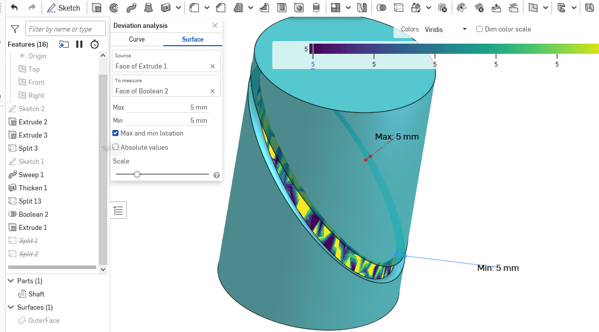
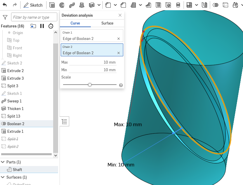
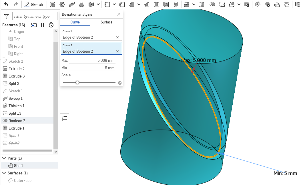
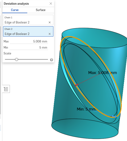
Last round for me… Since using a ruled surface methods introduced potential boolean errors and move face and move boundary was creating deviations for me…. I used Used a thickened swept surface and ended up with zero surface deviations and .008mm edge deviation (I don't really understand that with the surfaces at zero). Close enough. Least amount of features = most amount of accuracy as far as I can tell and easier for someone to duplicate. The dihedral angle deviations at the top of the slot at 2.87° and at the bottom of the slot 3.53°. Here's the link.
Note: This is much like the ruled surface method. but with a sweep surface instead so I didn't have to use move face/boundary and added split provision to keep the base of the slot "flat". After settling in on the swept thickened surface I went back and used a ruled surface instead and ended up with pretty much the same results once I centered the geometry on the tool path. That's in the second parts studio. Feel free to pick it apart.
 0
0 -
Thanks for taking the time.
I tried to access the document via the link above and got a (transient and therefore uncopyable) error message that read (something like)
"Document failed to load for workspace. Either the document does not exist, or you do not have permission to load it."
Perhaps I was just too eager, and by the time this post gets authorised, that will be fixed. Or perhaps…
Anyway, thankyou for the time you've taken on this; I've learnt a lot from exploring your models..0 -
Sorry forgot to make it public. check it now.
0 -
With some more analysis I see the issue you are taking about. A few years back I did an analysis of the same thing on a spiral for a customer. The other issue I ran into was attempting to using a milling cutter.(he did not have any advantage of CNC equipment) Since the cutter direction of tool travel relative to part is at an angle the cutter doesn't reach the bottom of the groove except at the center. I think he could have lived with that by insisted keeping the pin away from bottom the grove but he insisted it would be square.
Back then I still had access to SolidWorks which has a tool path generator which confirmed what the bottom of the groove would look like. If the square bottom is a must it can be finished with single point tool. This one has the addition of looping back on it's self. Bit of a pane.
I went back and used a thickened surface to create groove.
0