Welcome to the Onshape forum! Ask questions and join in the discussions about everything Onshape.
First time visiting? Here are some places to start:- Looking for a certain topic? Check out the categories filter or use Search (upper right).
- Need support? Ask a question to our Community Support category.
- Please submit support tickets for bugs but you can request improvements in the Product Feedback category.
- Be respectful, on topic and if you see a problem, Flag it.
If you would like to contact our Community Manager personally, feel free to send a private message or an email.
Need help troubleshooting LOFT_FAILED
 dave_cowden
Member, Developers Posts: 484 ✭✭✭
dave_cowden
Member, Developers Posts: 484 ✭✭✭
I have automatically created a couple of faces using skFitSpline. They appear closed correctly.
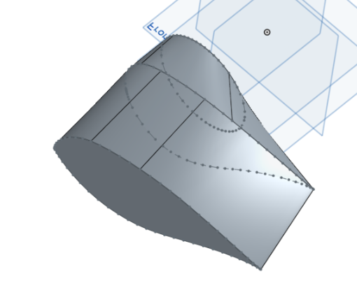
But no matter what I try, I cannot loft them. I get LOFT_FAILED.
Here's what they look like:

I don't really want to bother anyone to have to look through all of the source code-- though I'm happy to share it if needed, it's a lot.
I mainly need pointers on how to learn why a loft is failing. In the above geometry, I have tried just about all combinations of options: all of the end conditions, match vertices, nothing works. As you can see, I tried providing a guide curve, as well as providing several guide curves: they do not work either.
The curves appear to be closed, because using guide curves, I was able to get each pair to loft to each other, like this:
This was done by connecting the first to the second, and then the second to the third, using different guide curves. But i cannot seem to get it to work using curves that connect all three faces.
Does anyone have pointers? This seems like it is harder than it should be.
thanks for any tips!
Dave
But no matter what I try, I cannot loft them. I get LOFT_FAILED.
Here's what they look like:
I don't really want to bother anyone to have to look through all of the source code-- though I'm happy to share it if needed, it's a lot.
I mainly need pointers on how to learn why a loft is failing. In the above geometry, I have tried just about all combinations of options: all of the end conditions, match vertices, nothing works. As you can see, I tried providing a guide curve, as well as providing several guide curves: they do not work either.
The curves appear to be closed, because using guide curves, I was able to get each pair to loft to each other, like this:
This was done by connecting the first to the second, and then the second to the third, using different guide curves. But i cannot seem to get it to work using curves that connect all three faces.
Does anyone have pointers? This seems like it is harder than it should be.
thanks for any tips!
Dave
0

Answers
another debug tool is : can you try selecting one segment (neighboring the guide) in each profile and see if you can create a surface loft with the guide? Basically, try creating a little ribbon right next to the guide.
Loft invalid message usually means there's a self intersection somewhere or bad geometry created with input. To figure out where it is happening exactly I would need access to your exact geometry.
I'll fiddle with it a bit more, and if i cannot get it to work, i'll create a ticket and then share the document with support.
Thanks for the response, i'm sure we can get it working.
LOFT_GUIDE_PROFILE_INTERSECTION.
Since it isn't, I'm afraid the issue is not related to that. LOFT_INVALID refers to self intersections so I'm guessing there's some sort of a twist that's getting created. Potentially near the multi-knot point.
You could try splitting your splines for each profile and see if you can create larger ribbons. (say, have 4 end-to-end spline curves for each profile) and experiment with picking corresponding ones from each profile and see if that works. This could at least point you to the location of the twist, which you can then help my adding a guide curve there.
I'm trying to create your geometry through the user interface:
It's not easy building through the interface. The circle is the only profile that required a pierce as the the spline profiles had a node coincident to all planes shown and didn't need a pierce.
- the tear drop profiles need to be 2 splines not one closed spline. Unless OS gives you a non-tangent closure for a spline which I'm sure it doesn't, you'll always have a radius. With 2 splines you can make one end tangent and leave the other coincident.
- also I noticed that you create a few nodes for your spline definitions. After you create these, you should run a fit spline to reduce node count. Not sure how parasolids handles this reduction, but the fewer the nodes the better.
as a rule of thumb, I've always counted the spline segments (# of nodes -1), then multiplied 12 (spline coefficients), the inverse blending matrix for a cajillion nodes is 12 cajillion numbers. Surfaces based on these splines will contain monster numbers and will produce solids with monster numbers. All this means is slow, and it never gets better. This happens a lot, especially when people use scanned data. I've seen some real nasty models because they never reduced the node count.
I haven't played with splines programmatically in OS yet. I'm hoping theres a way to define a spline using the magnitude vectors as opposed to using a cajillion nodes. I'm hoping for a curve fitting algorithm that computes curves based on least number of nodes and using the spline handles. SW didn't do this, infact I've never seen this. Hoping a math wizard comes up with this curve fitting algorithm because I need it in my scanning feature script.
They say that parasolids won't show uv curves on a surface, but it would be helpful to have these curves show up at node positions. This way you can see how tight a surface definition is without inspecting the curves used to build the surface.
Creating clean geometry should be a goal to keep system responsive.
My profile definition (2 splines):
While it isn't programmatic, you can try making a sketch on each of the faces generated, project/use the spline and try to split the spline at a couple points (I am thinking 4 at the major/minor axis) and try lofting with those profiles.
Thanks for all the feedback!
These splines were imported from data in an external program-- thus the quantity of them. The points where created using code like this ( roughly )
Here's the code i'm using ( pointList is a list of points in sketch coordinates from an external source ):
<div> var sketch = newSketchOnPlane(context, sketchPlaneId, {</div><div> "sketchPlane" : plane</div><div> });</div><div> </div><div> for (var j=0;j<size(pointList);j+=1){</div><div> skPoint(sketch, "point1"~j, {</div><div> "position" : pointList[j]</div><div> }); </div><div> } </div><div> </div><div> skSolve(sketch);</div>I did find that removing a bunch of points does eventually make the lofts work. I had to remove about 60% of the points, and though the curves dont really look exactly like the input at that point, the loft does work.
I haven't played with splines programmatically in OS yet. I'm hoping theres a way to define a spline using the magnitude vectors as opposed to using a cajillion nodes. I'm hoping for a curve fitting algorithm that computes curves based on least number of nodes and using the spline handles. SW didn't do this, infact I've never seen this. Hoping a math wizard comes up with this.
Yeah it seems that reducing the complexity is key. The problem is, I dont think there's any routines in FS that help simplify a spline while keeping its definition the same.
Do you mean skFitSpline? Or something else?
Ok so i'm getting closer!
The screenshot below is the result of modifying code to limit the number of points in each spline. So instead of a cajillion points per spline, now I have cajillion/10-- I just started a new spline every 10 points.
This made the profile loft with no trickery:
The only problem left is the odd twist between the bottom two profiles and the circle at the top.
I tried to fix this by adding a guide curve ( i just fit a spline through three points). But that results in an invalid loft. SO in this case, I know that the invalid loft is related to the guide curve, not the splines themselves. Ideas?
I tried that-- still Loft failed. Interesting also: i tried selecting both guides individually, as well as both at the same time, and none of those lofts worked:
Now that this time i have lots of little-er splines, I also tried your earlier idea of choosing ribbons ( of course those are surface lofts). I tried a ribbon on either side of both of the guides ( since each guide is at the point that borders the different splines. All 4 ribbons worked
Ok, so the guides work when used with ribbons, and an unguided loft works excepts twists between the circle and the first foil. But the lofts do not work with either guide selected....
Failing that, I would have to ask you again to submit it via the feedback tool, so that we can debug deeper.
@elif i'll clean this up and place a support ticket. Thanks for the help thusfar!
Your guide curves have to 3 nodes. Also, unless you're using a 3d spline to connect them, you'll have to insure u-curves have a node point on a plane that you're defining the v-curves (guide), all these nodes must match each other in location (space). This is really painful geometry without construction planes & geometry. All curves must share the exact node location to have u-curves & v-curves connect. It's hard for me to see if your curves are intersecting at nodes. I also think getting a 2d guide curve to work programmatically would be impossible.
Remember surfaces are connected based on the % length along the u-curves. Matching lengths will make things flow more easy.
This is magic, parasolids does a good job with un-matched vertices (pro/e wouldn't do this, had to match vertices):
I have a circle profile and a 2 spline profile and most would think the v-curves start at the tail of the 2 spline profile and work their way around based on length of profiles ie.. when I'm 50% through the 2 spline profile then I should be 50% through the circle profile. How does parasolid know where to start on the circle? Don't know it's magic and it works pretty well.
This is how most CAD systems want this done (vertex matching, pro/e required this). Where do the v-curves start and end? It's pretty easy when you lay it out this way. The v-curves correspond to the completion of the top arc to the completion of the one spline segment (you're at 60% length on the arc then you're at 60% length of spline).
This surface is natural meaning there's nothing causing it to be nothing but a straight line between the arc and the spline. It's the same thing using a 2 noded spline and not pulling on the control handles. We use to explain this as the shortest distance possible between 2 points. That's what happens when you don't tense up a 2 node spline using handles. You get a line.
What if you didn't want linear v-curves? Then you add guide curves.
I used the 3D spline tool Ilya wrote in the beginning featurescript so I wouldn't have to insure my guide curves lied on a -plane and that there were shared vertices between my u-curves.
Things to try:
-match node count in each profile, 10 for circle, 10 for 2nd spline profile and 10 for the last.
-I wouldn't use guide curves, use vertex matching instead. If you want guide curves, create 3D splines.
-Reduce node count. My shape look better than yours, easier to manipulate and is a ton faster. Nodal count is everything when surfacing.
In the end, once you have your pinched up a surface with 40 nodes, you'll have to trim it, extend it, knit it, ruled surface the ends and make a manifold. All this works better on well defined surfaces. I'm not sure programmatic surfaces are ready for this. Surprise me.
Thanks for helping!
It's hard for me to see if your curves are intersecting at nodes. I also think getting a 2d guide curve to work programmatically would be impossible.I used a trick for that-- i have a custom programmed feature: "Fit spline to selected points". So to create 3d splines for the guide curves that i know pass through each profile, I just select the three points i want and do "fit spline to points". In this case, the nodes on the profiles help me: i have already-made nodes on each profile I can select.
I agree-- my guides are already 3d splines
I agree here also, but i am not sure how to accomplish it programmatically. I can do it visually of course, and there is no doubt that the trouble here is due to the increased number of nodes. But i dont want to have to resort to manual reduction. Though i agree this is probably the solution, it just might not be easy.
I've used fitspline to create a line. I think it's create a spline and maybe should be called createspline.
Node reduction is something we'll need. Took forever to get it in SW, then they created a spline you couldn't work with, a p-spline or something. I'll rag on if they generate non-user workable splines. Give me an option to create noded splines vs. some computed spline.
I've been watching scan to cad code for over 20 years and everyone creates a mess. Parasolids has a new mesh convertor out and hopefully we'll see some cool algorithms converting points to surfaces soon. I'm not holding my breath though.
Thinking about what Jake Ramsley posted, I'd do what he suggests with a twist. I'd compute the length of each profile. Then divide this length by 4. When laying your points down compute the total length after adding each point. When you reach that length/4, stop and create a vertex. Match all your profiles with 4 vertices and loft using 4 matching vertices. Will it look right, some times. How do you know where to start and stop? May require some magic. Do you have an ordered set of points or a random set of points? They appear ordered with a start and stop. Use what you have.
Welcome to the world of reverse engineering. It ain't that good...
Do you know of a way to take these points:
and fit a 2 noded spline through them (within a tolerance):
and end up with a 2 noded spline:
I found some algorithms to do it, but they are not trival.
I do a lot of surfacing for customer's products and rarely use anything greater than a 2 node spline. Sometimes a 3 noded spline (2 segments), but not often. For me, these things stack up. That one surface will have 40 to 50 subsequent steps until I knit into a manifold. Building clean base geometry is the reason I can complete a project where most fail. It's not magical, it's just well thought out.
I'm not sure an interpreted script would be fast enough. I think this has to be in the core. Even if you did compute the coefficients for each segment, how are you going to get them back into the system? There's no mechanism for that.
I don't think the average user will create 40 noded splines on their own. But us guys that are using computed points or scanned data will easily hit this and higher. My data set is 50k points and I have to figure out which 3 to use. I feel a real need for nodal reduction for us guys bringing in point data.
I've started looking at the library to see what's available for splines. The code blocks on this forum appear to be broken. Could you post your create sketch & spline code. Seems like I saw it once although it was all on one line. Reviewing the 3Dspline & skspline, I don't see any access to the spline handles. I did check SW api and you do have access to the handles and I think you can set them which is a good thing. Not sure you can set one that hasn't been set by the user. Checked the SW code for fit spline to see what gets returned, couldn't find anything. I don't think it's a b-spline, which is what we want.
In SW the fitspline requires 2 splines which is a bug. Also you'd think with enough tolerance I could turn these 2 splines into a straight line but that never happens. This has a tolerance of 124mm and I get a reduction of 2 nodes. Look at what it's reporting back 3 splines, they don't tell you what type of spline they are. The node reduction algorithm in SW has changed over the years and think this one isn't very good. Seems to have been better in this past.
Currently I'm planning manually creating curves by looking at where the points lie. It would be nice to automate this but I'm not sure this is possible at this time.
Dave, if you figure this out, please share,
I did the same review and i agree. There are currently no tools available in the FS api that would viewing or manipulating the control points. The only possible approaches will be to compute nodes that are redundant and remove them.
Given a profile with 100 nodes, it is highly unlikely that a tool which can only remove nodes will successfully replicate the geometry,without ability to manipulate the control points.
I'm afraid right now there is not a happy ending to this story. FS is a dead-end unless the api changes.
SOOOOO, now, i'm taking a new strategy-- i'm researching using the API with the idea that I can build this functionality externally, and then use that to create features.
@billy I think you are the author of the timecard application, right? Do you mind giving me some pointers on where i can learn about the Onshape application api? I keep looking for the 'high level docs' but can't find it.
Our API has support for programmatically adjusting the values within features on the feature list (and adding/removing etc items from the feature list) which may help you with what you're trying to do (the API also supports broader document/workspace level metadata access etc. and import/export)
It cracks me up when someone thinks they'll take a picture of an object with an ipad, print it out and put it on their formula one race car. The boys at occipital think it's right around the corner.
App Store:
Talk to Joe Dunne, he'll get you codes.
As far as how, you just ping a server and you'll get back json. You run inside an iframe which is your site in their site. You have to have css which is freaking expensive.
If you're having issues, let's take offline, not sure I'm suppose to be talking about it.
I have some great ideas, if you combine featurescript with app store, watch out! Depending on who you ask, you'll get different answers weather they're talking to one another and I haven't researched it yet. I think the hooks are there.
Looking into python, how do you serve up python on the web? Do you have your own private server or are you sharing a hosted server?
Surface cusp, not liked by solid modelers. #1 reason a loft will fail.
I suspect this edge and the 2 surfaces being created are interlaced:
I don't believe OS is complaining about the monster task at hand (you want me to do what?) and will create the geometry if you remove the cusps. I just worry about the system response once you do it get it working.
Once/if it is working you'd have one feature that used up a gig of ram, I guess that's something to be proud of.