Welcome to the Onshape forum! Ask questions and join in the discussions about everything Onshape.
First time visiting? Here are some places to start:- Looking for a certain topic? Check out the categories filter or use Search (upper right).
- Need support? Ask a question to our Community Support category.
- Please submit support tickets for bugs but you can request improvements in the Product Feedback category.
- Be respectful, on topic and if you see a problem, Flag it.
If you would like to contact our Community Manager personally, feel free to send a private message or an email.
Drive a Linear Pattern Using an Array?
 jackson_king
OS Professional Posts: 80 PRO
jackson_king
OS Professional Posts: 80 PRO
Hi All,
Is there a way to get a linear pattern to vary the instance spacing based on a #variable that contains an array of values?
The use for this is to create a feature pattern of mate connectors or holes in a part studio.
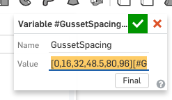
As you can see the row of mate connectors directly under the holes, these features go in at the same spacing as the purple gussets and I would like to be able to drive patterns for the mate connectors and holes using a #variable containing an array (shown above).
There are several variations of this cylindrical tank with decks on the side and I would like a good way to put in a lot of info (arrays) and get the varied spacing I am looking for.
Thanks, Jackson
Is there a way to get a linear pattern to vary the instance spacing based on a #variable that contains an array of values?
The use for this is to create a feature pattern of mate connectors or holes in a part studio.
As you can see the row of mate connectors directly under the holes, these features go in at the same spacing as the purple gussets and I would like to be able to drive patterns for the mate connectors and holes using a #variable containing an array (shown above).
There are several variations of this cylindrical tank with decks on the side and I would like a good way to put in a lot of info (arrays) and get the varied spacing I am looking for.
Thanks, Jackson
0
Best Answers
-
 mahir
Member, Developers Posts: 1,321 ✭✭✭✭✭
Sounds like a job for configurations. To be continued...6
mahir
Member, Developers Posts: 1,321 ✭✭✭✭✭
Sounds like a job for configurations. To be continued...6 -
 oleg_shilovitsky
Member, Developers Posts: 131 PRO
jackson_king said:#Dylan_Stewart & #mahir, thank you for your comments! Where have you found good resources for learning more about featurescript?
oleg_shilovitsky
Member, Developers Posts: 131 PRO
jackson_king said:#Dylan_Stewart & #mahir, thank you for your comments! Where have you found good resources for learning more about featurescript?
I have also asked #oleg_shilovitsky about having a way to use an OpenBOM like table to drive the variables or reference the table directly from the dimensions. I think both could have equal validity in practice.
The reason I wanted to array the driving dimensions is illustrated below:
There are many that are tied to "compartment 1", then "compartment 2", etc. as there are 3 compartments to this tank and each have about the same plumbing holes cut in it.
@jackson_king
Very interesting idea how to use openBOM for configurations.5 -
 Dylan_Stewart
Member, Developers Posts: 107 PRO
@jackson_king I use the FS library, FS forums, FS webinars and @lougallo @ilya_baran and @cody_armstrong to get started using FS. Everyone has been more than helpful and I'm sure will help you get over your speed bumps. I can help (where I can) but those guys will probably be able to get you set up.
Dylan_Stewart
Member, Developers Posts: 107 PRO
@jackson_king I use the FS library, FS forums, FS webinars and @lougallo @ilya_baran and @cody_armstrong to get started using FS. Everyone has been more than helpful and I'm sure will help you get over your speed bumps. I can help (where I can) but those guys will probably be able to get you set up.
Digital Engineering5 -
Dylan_Stewart
Member, Developers Posts: 107 PRO
"team" work makes the dream work!!!!
 Digital Engineering6
 -
 cody_armstrong
Moderator, Onshape Employees, Developers, csevp Posts: 221
cody_armstrong
Moderator, Onshape Employees, Developers, csevp Posts: 221  @jackson_king Please take a look at this public model of using arrays in patterns. I think this is similar to what you are asking.
https://cad.onshape.com/documents/8ba8f542acbba774726bc830/w/0f1f32a1cdf32489b727efa4/e/6dcc5e4b7c2375c65da14d9d
5 -
mahir
Member, Developers Posts: 1,321 ✭✭✭✭✭
@jackson_king, I just remembered there is a point pattern featurescript written by OS I believe. It's not the same as driving a pattern with an array, but you can get the similar results by driving a pattern with a bunch of independently dimensioned points.5
-
cody_armstrong
Moderator, Onshape Employees, Developers, csevp Posts: 221
@jackson_king Here is a simple example of patterning mate connectors based on sketch point locations using FeatureScript.
https://cad.onshape.com/documents/57cf1a62dfdcf610c72f3c76/w/b957914f796545e00f196d60/e/407aa1a7b47f5776f5cf649c
I will update the Point Pattern to support features soon.6
Answers
Have you tried that yet?
I have also asked #oleg_shilovitsky about having a way to use an OpenBOM like table to drive the variables or reference the table directly from the dimensions. I think both could have equal validity in practice.
The reason I wanted to array the driving dimensions is illustrated below:
There are many that are tied to "compartment 1", then "compartment 2", etc. as there are 3 compartments to this tank and each have about the same plumbing holes cut in it.
@jackson_king
Very interesting idea how to use openBOM for configurations.
Probably by the time I get around to this, Onshape will have rolled out some awesome new capability for handling this situation.
I also have a feeling that @oleg_shilovitsky has a few tricks up his programming sleeve too! So if I just procrastinate long enough, it will get fixed;)
https://cad.onshape.com/documents/8ba8f542acbba774726bc830/w/0f1f32a1cdf32489b727efa4/e/6dcc5e4b7c2375c65da14d9d
I tried looking through things a little and could not find how to allow me to select a MC for pattern (not sure what to set the filter to?).
This may be more of a moot point as OpenBOM just released an update and now I can "group by name" and that should let me have multiple instances of the same part in a particular part studio and be able to treat them as the same in the BOM.
https://cad.onshape.com/documents/57cf1a62dfdcf610c72f3c76/w/b957914f796545e00f196d60/e/407aa1a7b47f5776f5cf649c
I will update the Point Pattern to support features soon.
I am trying to get the spacing between the patterned instances to vary based on the array set up as a variable. Let's say I want to pattern the square bars in the "ladder" example you linked above; I want the 1st bar (instance/seed) to be at zero, the 2nd at 3", the 3rd at 10", the 4th at 14", & the 5th at 27.5". I was trying to set up an array as variable to look like this, [3,10,14,27.5][VariedSpacing]. Then in the spacing spot in the linear pattern I would call #VariedSpacing and put in 5 for the # of instances.
I hope I was able to be more clear on this!! It makes my head hurt when I try to explain it;)
This in itself will be a big time saver for me! Onshape rocks!
Thanks, Jackson
Thanks, Owen S.
HWM-Water Ltd
If you have a sketch point (an arc center for example), you can use the Point Pattern feature to accomplish something similar to this.
One more thing. This may not be the best technique if each "rivet" you mentioned is a separate instance of a part. Multiple instances of parts is best handled at the assembly level so you can ensure the quantity counts are correct. This would mean you would use the actual Replicate command in Assemblies to accomplish this.