Welcome to the Onshape forum! Ask questions and join in the discussions about everything Onshape.
First time visiting? Here are some places to start:- Looking for a certain topic? Check out the categories filter or use Search (upper right).
- Need support? Ask a question to our Community Support category.
- Please submit support tickets for bugs but you can request improvements in the Product Feedback category.
- Be respectful, on topic and if you see a problem, Flag it.
If you would like to contact our Community Manager personally, feel free to send a private message or an email.
What is the best way to offset vectors depending if they're positive or negative?
 Lee_Hesketh
Member, Developers Posts: 148 ✭✭✭
Lee_Hesketh
Member, Developers Posts: 148 ✭✭✭
Hello all, I have come across a peculiar error in my code. I am using a vertex as a reference point for the first corner of an skRectangle(). I am using worldToPlane() to achieve this. I am then adding a vector which is offsetting the first corner in relation to the vertex. It looks like this:
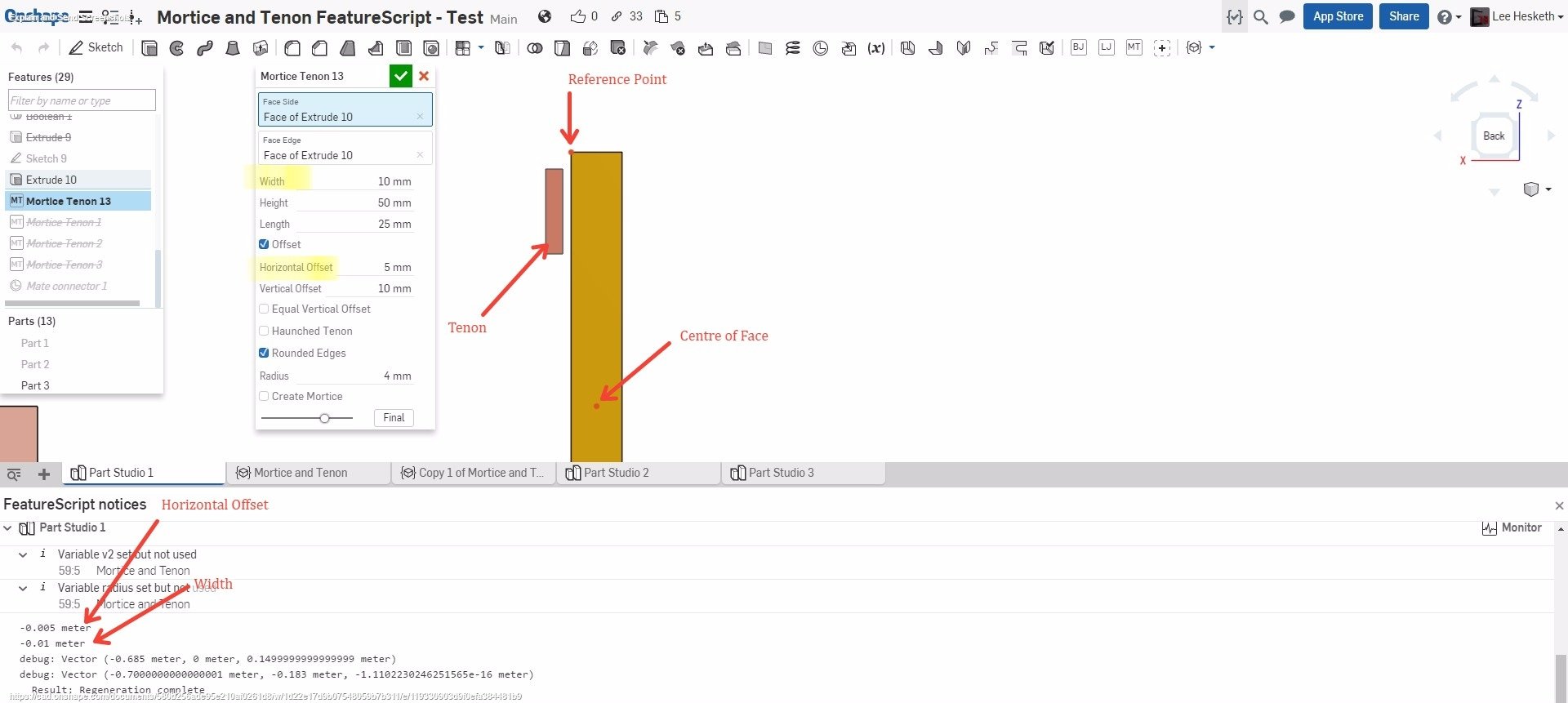
I am making h and width positive or negative by using the reference point and the centre point of the face, as seen by the two red dots. I am doing this by adding the difference in x coordinates and the difference in y coordinates. R = reference point, C = centre point
Since this featurescript will be used on parts such that the face shown is aligned with either the X or Y axis, that is why I am adding both X and Y coordinates. For example, in the picture, the Y coordinates of R and C are equal since they are on the same plane. This means that (R[0]-C[0])+(R[1]-C[1])
is the same as R[0]-C[0]. If this value is greater than 0, R is more positive than C and therefore h and width should be negative. And so to the error. I debugged h and width and they are indeed negative. However, the resulting geometry, the red part labelled Tenon, is going the other way and I don't know why.
Could anyone either explain what I'm doing wrong or suggest an alternative to achieve that same thing?
Document:https://cad.onshape.com/documents/580b256ade95e210af0261d8/w/1d22e17d9b07548059b7b311/e/119330903d9f0efa384481b9 , "Mortice and Tenon"
Thanks
Lee Hesketh
skRectangle(sketch1, "rectangle1", {
                        "firstCorner" : worldToPlane(evPlane(context, { "face" : comps.sketchFace }), comps.vertexPoint) + vector(h, -v1),
                        "secondCorner" : worldToPlane(evPlane(context, { "face" : comps.sketchFace }), comps.vertexPoint) + vector(h + width, height)
                    });
I am making h and width positive or negative by using the reference point and the centre point of the face, as seen by the two red dots. I am doing this by adding the difference in x coordinates and the difference in y coordinates. R = reference point, C = centre point
if((R[0]-C[0])+(R[1]-C[1])>0)
    {
      h*=-1;
      width*=-1;
    }
Since this featurescript will be used on parts such that the face shown is aligned with either the X or Y axis, that is why I am adding both X and Y coordinates. For example, in the picture, the Y coordinates of R and C are equal since they are on the same plane. This means that (R[0]-C[0])+(R[1]-C[1])
is the same as R[0]-C[0]. If this value is greater than 0, R is more positive than C and therefore h and width should be negative. And so to the error. I debugged h and width and they are indeed negative. However, the resulting geometry, the red part labelled Tenon, is going the other way and I don't know why.
Could anyone either explain what I'm doing wrong or suggest an alternative to achieve that same thing?
Document:https://cad.onshape.com/documents/580b256ade95e210af0261d8/w/1d22e17d9b07548059b7b311/e/119330903d9f0efa384481b9 , "Mortice and Tenon"
Thanks
Lee Hesketh
There are 10 types of people in the world. Those who know binary, those who don't and those who didn't expect base 3!
Tagged:
0
Best Answer
-
 billy2
Member, OS Professional, Mentor, Developers, User Group Leader Posts: 2,143 PRO
Lee-try this
billy2
Member, OS Professional, Mentor, Developers, User Group Leader Posts: 2,143 PRO
Lee-try this
I want to draw on this face highlighted below:
To create a sketch, use this vector to offset the sketch:
Use the face normal for direction, this is the sketch Z direction and
also called the sketch normal:
Use this edge to orient the X axis on the sketch:
This creates a sketch where the bottom left corner is 0,0 and the axis are aligned properly:
Now it's pretty easy to position the sketch rectangle. Just extrude it, the face normal set the sketch up so positive comes out of the part.
If you're going to use sketches, use the 3 vector method and position the sketch properly. You shouldn't have to think about the math or abs(X) or any of that stuff.
5
Answers
Was poking around in your code. I have no solutions to your problem. Just some observations.
1st-
change part studio units to meters, it makes debugging this stuff much easier. You can use the measure tool and see which coordinate system your comps object is using.
2nd-
I have no idea what this is initialComputations(context, id, definition); I checked documentation and found nothing. What's it returning?
With units set to meters, I can understand comps object:
Trying to find something meaningful in comps object:
I don't like comps. Seems useless to me.
I don't trust this at all because of the comps query, shouldn't have to compute h or width:
Can't you query the face or edge and get better properties?
comps is some kind of 3D object I'm assuming it's the body of your face query. I did probe it looking for some meaningful data. centerpoint & centerpoint2 are useless. centerpoint of what?
I think you're barking up the wrong tree with comps. I'd look for a better query. The math should work itself out once you get good a query.
Onshape can you please give us a function that prints an object in an indented format?
I feel like I'm being punished for something when viewing an object.
Comps is just a variable that calls initialComputations so I don't have to retype the whole thing. So when I want to get say vertexPoint, since it is in initialComputations, I call it by using comps.vertexPoint. When you printed comps, you printed the entire map.
CentrePoint 1 and 2 are the centres of the two end faces, in this case, the faces that are in the XZ plane. I need centrepoint1 because I am using that to determine if h and width should be either positive or negative. Both centre points are need later on when creating the mortice. I am using them to find any parts that contain those points. They are hidden in the part studio, but these are the targets that I use when performing a Boolean operation with the tenon.
H and width are not calculated, they are values the user inputs, width and horizontal offset.
The problem still remains. If you unsuppress mortice tenon 2, you will see that it works as expected. It only doesn't work on parts perpendicular to it and I don't know why.
maxCorner equals vertexPoint and is world coordinates:
minCorner is world coordinates:
I'm going to stick my neck out and say that initialComputations() is returning world coordinates.
This is the h & width stuff that I'm not sure about:
Seems like if it's set up properly, you shouldn't have to worry about direction.
Below, the sketch creation scares me. I don't think you have control over the sketch transformation OS is returning and could be flipping horizontal & vertical. I'd feel more comfortable defining this sketch with 2 vectors and removing the ambiguity. OS uses some patterns to generate sketches (as far as it's transformation is concerned), but I'm not sure you can rely on it consistently. Will horizontal always be to the right and vertical is up? I don't think so. Width & height are based on horizontal & vertical?
I'll look at your working example and see if the newSketchOnPlane composition is the root of the problem. This seems ambiguous to me not sure I'd rely on it. Without knowing horizontal & vertical I don't think width & height make sense.
https://forum.onshape.com/discussion/5184/vector-coordinates-help#latest
If I were going to write one, I probably wouldn't use any sketches. I was thinking you'd need the inner & outer edges shown below & a tab length:
From here I'd create some sheets:
Then work some magic:
I don't think I'd dance through a bunch of sketches and create mortice tenons as if building it with the user interface.
It'd be cool to mortise & tenon this:
This is determinate, but I have another piece of info (rectangle center):
But what's X or Y? Is it +X or -X? Depends on which quadrant you're in. It's based on the transformation they used to get you into a sketch.
I think you're going to have a real mess on your hands keeping all this straight.
I'm using the user's interface.
-I've created sketch 10
-I have no idea what horizontal and vertical are, but who cares
-I've worldtosketch these points so now they're in sketch10 coordinate
So you know
-vector p2-p1
You also know
-vector p3-p1
These are the same vector direction, so p3 is useless to you
You need p4 and you need to know that's it's the width:
-unitize(vector p4-p1)* width, here's your width
From p4 you can get p5
-unitize((p4-p1 cross with Z) cross with (p4 - p1))*height, using a triple product
I don't think you can get p4-p1 from your query. Your problem is indeterminate.
To get the extrude direction you can ckeck the dot product between the sketch normal and the face normal possibly returned in comps.
sketch10 width & height are meaningless unless you compose the sketch transformation using p4-p1. If you know p4-p1 then screw the composition of the sketch transformation and perform the vector math in sketch (width & height won't match vertical & horizontal).
My point, without knowing p4-p1, can't solve the problem.
My point about in/out of sketches is that it's a nightmare keeping it straight.
Let me know if you get it working,
centrePoint1 & centrePoint2 are the centers of the extruded faces. Where's the center points for top & bottom extrudes? What if I extrude a hex?
centrePoint trying to understand why it's not centerPoint,
Did you write initialComputations() or did OS?
So the normal to sketch 10 in your example is the Y axis. In my picture, the red part should be inside the yellow part like this.
To achieve this, I have entered in a horizontal offset of -15mm. Which essentially, if the code worked correctly, is a 5mm offset and a 10mm tenon width. This is a workaround but I want it to work first time.
My fear is that you'll get it working for this case, but when you spin the part around to the back side and try it, it'll be wrong.
I'm not sure all this will be robust enough to work all the time.
Are you automatically going to find the mating part or does the user pick it. Is it 1 sketch that cuts /extrudes or 2 sketch transforms with each part getting it's own sketch? If you use 2 sketches, remember you have to go from sketch1 to world and then from world to sketch2. There is no from sketch1 to sketch2.
This one seems more trivial than the mortice and tenon.
I think in CAD they'll ask for X and then Y. Y doesn't have to be orthogonal X.
I've never created a sketch based on 2 vectors. Hopefully you can. It seems to me, sketches defined on faces use the minimum number of translations. If you looked normal to sketch10 and it's origin, that would match the world origin. The rotations are magic. There's multiple solutions and which ones they have chosen to create a sketch on a face, I'm not sure.
A triple product does all the magic.
Triple product is:
Z crossed with X -> gives you Y
Y crossed with Z ->gives you an orthogonal X
Triple products give you 3 orthogonal vectors. A coordinate system, sketch, circle......
-pick some 3D curves and extrude this way along this vector. opExtrude doesn't have a sketch dependency.
Here's your sketch based on 2 vectors:
It actually takes 3 vectors.
I think a triple product is easier.
annotation { "Feature Type Name" : "sketch" } export const myFeature = defineFeature(function(context is Context, id is Id, definition is map) precondition { annotation { "offset" : "My Query", "Filter" : EntityType.EDGE, "MaxNumberOfPicks" : 1 } definition.offset is Query; annotation { "normal" : "My Query", "Filter" : EntityType.EDGE, "MaxNumberOfPicks" : 1 } definition.normal is Query; annotation { "x" : "My Query", "Filter" : EntityType.EDGE, "MaxNumberOfPicks" : 1 } definition.x is Query; } { // println( // evLine(context, { // "edge" : definition.offset // }) // ); println(evCurveDefinition(context, {"edge" : definition.offset}).direction); println(evLength(context, {"entities" : definition.offset})); var offset=vector(evCurveDefinition(context, {"edge" : definition.offset}).direction)*evLength(context, {"entities" : definition.offset}); var normal=vector(evCurveDefinition(context, {"edge" : definition.normal}).direction)*evLength(context, {"entities" : definition.normal}); var x=vector(evCurveDefinition(context, {"edge" : definition.x}).direction)*evLength(context, {"entities" : definition.x}); println(offset); println(normal); println(x); var sketch1 = newSketchOnPlane(context, id + "sketch", { "sketchPlane" : plane(offset, normal, x) }); skLineSegment(sketch1, "line1", { "start" : vector(5, 0) * millimeter, "end" : vector(50, 0) * millimeter }); skLineSegment(sketch1, "line2", { "start" : vector(0, 5) * millimeter, "end" : vector(0, 35) * millimeter }); skSolve(sketch1); });I want to draw on this face highlighted below:
To create a sketch, use this vector to offset the sketch:
Use the face normal for direction, this is the sketch Z direction and
also called the sketch normal:
Use this edge to orient the X axis on the sketch:
This creates a sketch where the bottom left corner is 0,0 and the axis are aligned properly:
Now it's pretty easy to position the sketch rectangle. Just extrude it, the face normal set the sketch up so positive comes out of the part.
If you're going to use sketches, use the 3 vector method and position the sketch properly. You shouldn't have to think about the math or abs(X) or any of that stuff.
This is what the plane should look like all the time. However.
Sometimes, the third axis that isn't the x or normal points the other way. How could I set it such that the plane looks like the first one all the time? Also, what do you mean by offsetting the plane?
I have managed to get my script to work now! I simply inverted the variables controlling the height of the tenon if the z coordinate of the cross of the x and normal was greater than 0. Thank you very much for your help and persistence, I finally understand why my script wasn't working in the first place thanks to you. Keep up the good work!
Thanks for the problem, I've been meaning to figure out sketches in featurescript. I think I too can create geometry with sketches now.
When you're done with your script, take a video and show me how it works.
Cheers!