Welcome to the Onshape forum! Ask questions and join in the discussions about everything Onshape.
First time visiting? Here are some places to start:- Looking for a certain topic? Check out the categories filter or use Search (upper right).
- Need support? Ask a question to our Community Support category.
- Please submit support tickets for bugs but you can request improvements in the Product Feedback category.
- Be respectful, on topic and if you see a problem, Flag it.
If you would like to contact our Community Manager personally, feel free to send a private message or an email.
help circular pattern for circular saw blade

frank26080115
Posts: 19 ✭✭
hmmm I'm trying to create a mockup of a circular saw blade, but I can't figure out how to make the circular pattern work in this case
in SolidWorks, I would've just selected Extrude 3 as the feature, pick an axis, and been done with it
in Onshape, I cannot select Extrude 3 at all, according to the help page, I can check "Face pattern" and select the faces of Extrude 3, which I tried, but that didn't work, probably because it had only 2 faces that do not enclose anything. I tried selecting the outer rim face as well but that didn't work either.
I also cannot figure out how to circular pattern a sketch before using extrude.
What is the right way to create this pattern?
Thanks
in SolidWorks, I would've just selected Extrude 3 as the feature, pick an axis, and been done with it
in Onshape, I cannot select Extrude 3 at all, according to the help page, I can check "Face pattern" and select the faces of Extrude 3, which I tried, but that didn't work, probably because it had only 2 faces that do not enclose anything. I tried selecting the outer rim face as well but that didn't work either.
I also cannot figure out how to circular pattern a sketch before using extrude.
What is the right way to create this pattern?
Thanks
0
Best Answer
-
I assume the angle between the edges/teeth of the first profile is 360/30 degrees such that the edges would line up perfectly? If so, this would fully cannibalize the face that the face pattern is trying to live on and will cause it to fail. If there is some distance between edges then using a face pattern is viable and you only select the two faces that make the tooth and not the third one you have selected (I assume it is the cylindrical face).
A way to accomplish this currently would be to change your cut extrude (I assume extrude 3) to a "New" to create a new part. At this point you can pattern this part 30 times and do a boolean subtract. This has no requirement of the new faces not completely removing the face.
1. Edit extrude and change type from "Remove" to "New". This creates a new part that I want to pattern around and eventually remove from my profile.
2. Start a circular pattern and select the part for the part to pattern, an edge or cylindrical face of the profile to give the direction and fill out the rest of the information as required.
3. Start a boolean and choose subtract. Select all of the patterned parts for the tool. I personally use cross-select, which has the side effect of getting the profile I want to remove from as well. You could also shift select the parts from the part list on the left.
4. If your profile is selected, clicking on it will deselect it from the tools.
5. Select the profile for the target. The result is the saw profile designed. Hopefully it looks better and more usable than mine.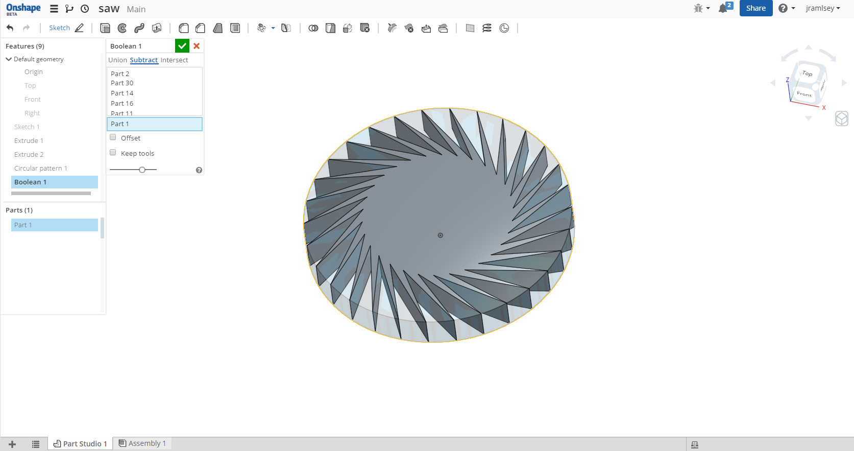
Jake RamsleyDirector of Quality Engineering & Release Manager onshape.com5


Answers
-
I assume the angle between the edges/teeth of the first profile is 360/30 degrees such that the edges would line up perfectly? If so, this would fully cannibalize the face that the face pattern is trying to live on and will cause it to fail. If there is some distance between edges then using a face pattern is viable and you only select the two faces that make the tooth and not the third one you have selected (I assume it is the cylindrical face).
A way to accomplish this currently would be to change your cut extrude (I assume extrude 3) to a "New" to create a new part. At this point you can pattern this part 30 times and do a boolean subtract. This has no requirement of the new faces not completely removing the face.
1. Edit extrude and change type from "Remove" to "New". This creates a new part that I want to pattern around and eventually remove from my profile.
2. Start a circular pattern and select the part for the part to pattern, an edge or cylindrical face of the profile to give the direction and fill out the rest of the information as required.
3. Start a boolean and choose subtract. Select all of the patterned parts for the tool. I personally use cross-select, which has the side effect of getting the profile I want to remove from as well. You could also shift select the parts from the part list on the left.
4. If your profile is selected, clicking on it will deselect it from the tools.
5. Select the profile for the target. The result is the saw profile designed. Hopefully it looks better and more usable than mine.
Jake RamsleyDirector of Quality Engineering & Release Manager onshape.com5 -
Thank you, that worked, but that action created 30 new parts, quite a clutter, and I'm not sure how to go back and change the number of teeth if I ever need to, without going through all these steps again.JakeRamsley said:A way to accomplish this currently would be to change your cut extrude (I assume extrude 3) to a "New" to create a new part. At this point you can pattern this part 30 times and do a boolean subtract. This has no requirement of the new faces not completely removing the face.
It might help if there was an option to create 1 new part that represented all 30.0 -
You can change the number of teeth by editing the circular pattern and changing the number of instances.frank26080115 said:
Thank you, that worked, but that action created 30 new parts, quite a clutter, and I'm not sure how to go back and change the number of teeth if I ever need to, without going through all these steps again.JakeRamsley said:A way to accomplish this currently would be to change your cut extrude (I assume extrude 3) to a "New" to create a new part. At this point you can pattern this part 30 times and do a boolean subtract. This has no requirement of the new faces not completely removing the face.
It might help if there was an option to create 1 new part that represented all 30.0 -
@frank26080115 Here's another quick example: public sawblade - feel free to examine. Sawblade frame is only 1 part (part1) but bits on teeth came out as independent parts, don't know how to combine.
@OnS Team: There should be a way to pattern a part in a way that it wouldn't create multiple new parts. Can't use boolean to combine if they don't intersect..
There was something weird happening with this model with the placement holes because I wasn't able to dimension them into place. Dimension was immediately greyed out as driven and if set to driving it would end up with over defined.. //rami0
 -
does patterning faces not work?
- Make a profile of the saw blade with one tooth
- extrude to thickness
- select circular pattern
- choose 'face pattern' in the circle pattern dialog
- select the faces making the tooth cut out
- choose the ring of the saw blade as the axis of pattern
- make the angular degree and tooth number and voila or...
- make the angular degree 360 and choose equal spacing and the appropriate number of teeth
0 -
And another example according to @Ben thoughts. Depending on the specs for tooth shape this might be the most simple way to achieve sawblade like models. Now I begin to understand the power of face pattern over feature pattern (we need both).
Found also reason for placement holes locking in place, OnS seems to create tangent connection to somewhere outside view which made dimensioning overconstrain immediately. Best way to learn is to do.
Here's another public sawblade link: Sawblade 2 //rami0