Welcome to the Onshape forum! Ask questions and join in the discussions about everything Onshape.

First time visiting? Here are some places to start:
  1. Looking for a certain topic? Check out the categories filter or use Search (upper right).
  2. Need support? Ask a question to our Community Support category.
  3. Please submit support tickets for bugs but you can request improvements in the Product Feedback category.
  4. Be respectful, on topic and if you see a problem, Flag it.

If you would like to contact our Community Manager personally, feel free to send a private message or an email.

Sweep with orientation control

brad_phelanbrad_phelan Member Posts: 85 ✭✭
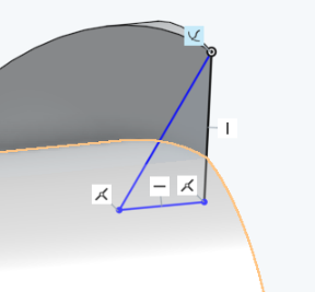
It seems that opSweep lacks orientation control. I am sweeping a profile around an axis on a helix and the profile never stays aligned to the helix axis. For example if I start with a sketch with the top of the triangle with a pierce constraint on the helix


I then apply a sweep but the profile swings wildly around. 

Ideally the following constraints should be maintained

X Axis of the profile plane should always stay parallel the cylinder axis.
The cylinder axis should be on the profile plane.

This blog post https://www.onshape.com/cad-blog/tech-tip-creating-a-thread suggest the process should work.

The problem may be that my helix is not strictly cylindrical as it part of an edge build by lofting.

However if opSweep had decent orientation control this should not be a problem

Tagged:

Comments

  • konstantin_shiriazdanovkonstantin_shiriazdanov Member Posts: 1,221 ✭✭✭✭✭
    look for Sweep normal FS by @mahir. it uses some hidden parameter of opSweep() to control profile orientation by reference surface normal.
  • brad_phelanbrad_phelan Member Posts: 85 ✭✭
    edited February 2018
    I have tried the Sweep Normal feature.


    and at first that seem correct but it is not. The profile does not maintain the alignment that a thread cut / generate would require. You can see at the end of the sweep that the orientation has been lost.


    The profile is now normal to the path. This is not what should happen.


  • brad_phelanbrad_phelan Member Posts: 85 ✭✭
    edited February 2018
    <<deleted>>
  • brad_phelanbrad_phelan Member Posts: 85 ✭✭
    The following featurescript does the job

    FeatureScript 749;
    import(path : "onshape/std/geometry.fs", version : "749.0");
    import(path : "b56c65d6f25a9054fdc2424c", version : "666e4832a96c6962a4a67a1c");

    annotation { "Feature Type Name" : "CylinderSweep" }
    export const myFeature = defineFeature(function(context is Context, id is Id, definition is map)
        precondition
        {
            
        // Define the parameters of the feature type
        annotation { "Name" : "Axis", "Filter" : EntityType.EDGE, "MaxNumberOfPicks" : 1 }
        definition.axis is Query;
        
        annotation { "Name" : "Profile", "Filter" : EntityType.FACE, "MaxNumberOfPicks" : 1 }
        definition.sketch is Query;
        
        annotation { "Name" : "Profile Origin", "Filter" : EntityType.VERTEX, "MaxNumberOfPicks" : 1 }
        definition.profileOrigin is Query;
        
        annotation { "Name" : "Path", "Filter" : EntityType.EDGE, "MaxNumberOfPicks" : 100 }
        definition.path is Query;


        }
        {
            var path = constructPath(context, definition.path );


            debugPath(context, path);
            var tangentLines = evPathTangentLines(context, path, range(0,1,100));
            
            var axis = evLine(context, {
                    "edge" : definition.axis
            });
            
            var planeS = evOwnerSketchPlane(context, {
                    "entity" : definition.sketch
            });
            
            var origin = evVertexPoint(context, {
                    "vertex" : definition.profileOrigin
            });
            
             var c0 = coordSystem(plane(origin, planeS.normal, planeS.x));
            

           // debugArray(context, tangentLines.tangentLines);
            
            var cs = mapArray(tangentLines.tangentLines, function(l){
                    var axisp = project(axis, l.origin);
                    var yAxis = line(l.origin,l.origin - axisp);
                    var zv = cross(axis.direction,yAxis.direction);
                    var zAxis = line(l.origin, zv);
                    var xv = cross(yAxis.direction, zAxis.direction);
                    var xAxis = line(l.origin, xv);


                    var cs = coordSystem(l.origin, xAxis.direction, zAxis.direction);
                    
                    var ts = transform(plane(c0),plane(cs));
                    return ts;


            });


            opPattern(context, id + "pattern1", {
                    "entities" : definition.sketch,
                    "transforms" : cs,
                    "instanceNames" : mapArray(range(0, size(cs)-1), function(n){return "tr"~n;})
            });
            
            debug(context, qCreatedBy(id+"pattern1"));
            
            opLoft(context, id + "loft1", {
                    "profileSubqueries" : evaluateQuery(context, qCreatedBy(id+"pattern1",EntityType.FACE))
                    
            });
            
            opDeleteBodies(context, id + "deleteBodies1", {
                    "entities" : qCreatedBy(id+"pattern1")
            });


        });


    and at the end the orientation is still correct


    It needs some tuning to pick the correct number of intermediate profiles but is more robust for this use case than the simple sweep.


  • mahirmahir Member, Developers Posts: 1,291 ✭✭✭✭✭
    If you link to your document, someone (possibly me) will almost always find a solution to your problem. I've found Normal Sweep to be pretty robust - more so than I would expect from something I quickly threw together. But it definitely requires well thought out inputs. It will maintain the normal orientation of your profile relative to a reference surface, regardless of your end goals or design intent. So make sure that reference surface actually meets the requirements for your design intent. Is the path coincident to the reference surface? Did your profile start out normal to the reference surface? Normal Sweep doesn't really keep the sweep profile normal. It just varies the profile orientation with the surface normal. So if you didn't start out normal, you won't magically get a normal profile. Either way, post a link. There's probably an easy fix.
  • konstantin_shiriazdanovkonstantin_shiriazdanov Member Posts: 1,221 ✭✭✭✭✭
    edited February 2018
    @mahir I think the problen with sweep normal may be in the fact that it doesn't extends reference surface
  • mahirmahir Member, Developers Posts: 1,291 ✭✭✭✭✭
    If that's the issue, then easy fix. Extend the reference surface prior to sweeping. If if it's a separate surface Normal Surface will accept multiple reference faces.
  • brad_phelanbrad_phelan Member Posts: 85 ✭✭
    I just don't think Normal Surface has the constraints that are required. The final position of the profile is kind of normal to the cylinder but it loses the original constraint that the plane of the profile should pass through the axis of the cylinder. Compare

    my solution

    to Normal Surface Solution


    The profile normal in both cases are tangent to the cylinder but because my solution has the addition contraint required for thread generation that the normal to the profile is always 90 degrees to the cylinder axis as well as being tangent to the cylinder.


  • mahirmahir Member, Developers Posts: 1,291 ✭✭✭✭✭
    Whatever works for you. As you said in your first post, it likely has something to do with your surface being non-cylindrical. I can't see your model, so I can't  really take an in-depth look.
  • brad_phelanbrad_phelan Member Posts: 85 ✭✭
    edited February 2018
    @mahir Sorry but can you explain how your solution could possibly work. I don't see any reason why the orientation should be maintained using your solution. Your solution just maintains that the normal to the profile and the surface normal under the curve are 90 degrees. Those are not enough constraints to keep the normal to the profile and the cylinder axis at 90 degrees. It just so happens that if you use a basic helix and a cylinder it doesn't drift.

    Here is a model using konstantin's sketch wrapping feature to generate an irregular wrap curve floating above the
    cylinder. I then try to sweep a triangle and keep it normal to the surface.However it drifts as I have described.


    https://cad.onshape.com/documents/deabd60eb1b75883cea24b8d/w/40f99b947624fdb9c98412b6/e/1c15780fa6cbf42d32cb7412

    I have linked my solution with the same curve and it doesn't drift.

    https://cad.onshape.com/documents/deabd60eb1b75883cea24b8d/w/40f99b947624fdb9c98412b6/e/ca2268fe0929c4e3130b0016

    ( there is a small bug in my sweep code. The profile is rotated 90 degrees in the profile plane during the sweep but this doesn't distract from the other issue being demonstrated )

    The end of the sweep with my solution


    The end of the sweep with Sweep Normal


    You can see that it my solution where I am much more explicit about the constraints the profile maintains it's correct orientation even under the stress of sweeping along such an irregular curve.
  • mahirmahir Member, Developers Posts: 1,291 ✭✭✭✭✭
    Someone needs to take a chill pill. No need to get defensive. As I said, whatever works for you. I just couldn't see exactly what you were trying to accomplish without a link to your document. I'm not claiming Normal Sweep is some magic feature that will work in every case. It's just a slightly modified version of opSweep I threw together on a whim. I'm on mobile now, but perhaps I'll take a look at your doc later as an academic exercise. 
  • konstantin_shiriazdanovkonstantin_shiriazdanov Member Posts: 1,221 ✭✭✭✭✭
    edited February 2018
    i would say Sweep is a specific case of more general feature like Loft, and sweep normal should internally behave like loft through a number of cross sections transformed along the path. the question is - what kind of transform is used. i noticed that ordinary sweep behaves as if it would use transform from initial tangent line of the path to the tangent line of current position. From this i can suppose that sweep normal uses transfroms from initial normal from starting point of the path to the ref surface to the normal line from the current path point. Documentation says that transforms from line to line uses the closest rotation that concides line directions so there remain some not fully defined "degrees of freedom", though line to line transform gives the most convenient profile orientation in general. But in specific cases it is obviously not enough for presize orientation control, and what Brad did - CS to CS transform is the most presize approach
  • brad_phelanbrad_phelan Member Posts: 85 ✭✭
    @konstantin_shiriazdanov The thing opSweep does which I don't yet is that it must figure out the optimum number of intermediate profiles to pass to the internal loft. So far I've just picked a number 100 but that may be too many or not enough. Is there an inbuilt method to turn a path into a piece wise linear curve using an error bounds? That might be enough to pick the points I need.
  • brad_phelanbrad_phelan Member Posts: 85 ✭✭
    I fixed the small orientation bug up with a new version of cylinder sweep.
    https://cad.onshape.com/documents/deabd60eb1b75883cea24b8d/w/40f99b947624fdb9c98412b6/e/ca2268fe0929c4e3130b0016
  • konstantin_shiriazdanovkonstantin_shiriazdanov Member Posts: 1,221 ✭✭✭✭✭
    edited February 2018
    @brad_phelani in Variable section sweep i personally use a profile per each 1 mm of the length of the path, without any guides. but it can be not very efficient. i think more advanced path partition for profile placement may be based on path curvature - the bigger the curvature the more profiles requared for a certain path area. the measure of curvature could be the angle step between two consecutive tangent lines (if path length parametrization for tangent lines used). this requares some heurisitc function which should return an array of length params for only points where consecutive tangents angular bias exeeds some user-defined value for example ~5 degrees. and in this case i think loft guides are requared since if you have straight enough piece of path only few section might be placed on it by this heuristic function
  • mahirmahir Member, Developers Posts: 1,291 ✭✭✭✭✭
    edited February 2018
    I took a look. As Konstantin mentioned, Normal Sweep does not constrain all degrees of freedom. Specifically, you can end up with a profile that is normal to the reference surface, but rotated about the normal vector at the end point of your path curve. The amount of rotation is entirely dependent on the path curve's normal vector at its end point. You can minimize this effect by using a profile that is normal to your path curve. This is how sweeps are usually performed anyway. Otherwise, it would be difficult to properly control the cross-sectional dimensions of your sweep. The more oblique your profile is relative to your path, the more exaggerated the effect. If you want the ends of sweep to not be normal to the path curve, then you can always overbuild and trim afterwards. But if your custom FS does the trick, that's cool.

    As for picking the right number intermediate profiles, I was thinking the same thing as Konstantin. Pick a tolerance for the max deviation of the normal or tangent vector at a set number of points along the path curve. Then, you can intelligently increase/decrease the number of subdivisions until you have the desired max deviation. Of course, this might be computationally expensive. Alternatively (if possible), you can add more intermediate profiles only where the path's curvature is greatest, leaving the straight sections with fewer profiles. Will opSweep allow you to choose the location of intermediate profiles?

    It's late. Goodnight.
  • mahirmahir Member, Developers Posts: 1,291 ✭✭✭✭✭
    Just noticed I got flagged. Pretty funny. No good deed...  :D  o:)  >:)
  • konstantin_shiriazdanovkonstantin_shiriazdanov Member Posts: 1,221 ✭✭✭✭✭
    edited March 2018
    by the way i think i found some useful orientation control function that takes into account both reference surface normal and path tangent.
    function evRefCS(context is Context, tangentLine is Line, refFace is Query) returns CoordSystem<br>{<br>&nbsp;&nbsp;&nbsp; var closestPointParam = evDistance(context, {<br>&nbsp;&nbsp;&nbsp;&nbsp;&nbsp;&nbsp;&nbsp;&nbsp;&nbsp;&nbsp;&nbsp;&nbsp;&nbsp;&nbsp;&nbsp; "side0" : refFace,<br>&nbsp;&nbsp;&nbsp;&nbsp;&nbsp;&nbsp;&nbsp;&nbsp;&nbsp;&nbsp;&nbsp;&nbsp;&nbsp;&nbsp;&nbsp; "side1" : tangentLine.origin<br>&nbsp;&nbsp;&nbsp;&nbsp;&nbsp;&nbsp;&nbsp;&nbsp;&nbsp;&nbsp;&nbsp; }).sides[0].parameter;<br><br>&nbsp;&nbsp;&nbsp; var faceNormal = evFaceTangentPlane(context, {<br>&nbsp;&nbsp;&nbsp;&nbsp;&nbsp;&nbsp;&nbsp;&nbsp;&nbsp;&nbsp;&nbsp;&nbsp;&nbsp;&nbsp;&nbsp; "face" : refFace,<br>&nbsp;&nbsp;&nbsp;&nbsp;&nbsp;&nbsp;&nbsp;&nbsp;&nbsp;&nbsp;&nbsp;&nbsp;&nbsp;&nbsp;&nbsp; "parameter" : closestPointParam<br>&nbsp;&nbsp;&nbsp;&nbsp;&nbsp;&nbsp;&nbsp;&nbsp;&nbsp;&nbsp;&nbsp; }).normal;<br><br>&nbsp;&nbsp;&nbsp; var dir = tangentLine.direction;<br>&nbsp;&nbsp;&nbsp; dir = dir - dot(dir, faceNormal) * faceNormal;<br><br>&nbsp;&nbsp;&nbsp; return coordSystem(tangentLine.origin, dir, faceNormal);<br>}
    and the transform requared is
    tr = toWorld(evRefCS(context, tangentLines[i], definition.refFace)) * <br>fromWorld(evRefCS(context, tangentLines[0], definition.refFace));
    it allow you to create things like this, which is not currently achivable by sweep normal or something else

    this type of profile orientation control is included in variable section sweep FS
Sign In or Register to comment.