Welcome to the Onshape forum! Ask questions and join in the discussions about everything Onshape.
First time visiting? Here are some places to start:- Looking for a certain topic? Check out the categories filter or use Search (upper right).
- Need support? Ask a question to our Community Support category.
- Please submit support tickets for bugs but you can request improvements in the Product Feedback category.
- Be respectful, on topic and if you see a problem, Flag it.
If you would like to contact our Community Manager personally, feel free to send a private message or an email.
3D Sketching in-context (wire rope)

I am evaluating Onshape as a possible replacement for Solidworks - for which we have been using for 20 years.
I am trying to create a wire rope routing around two sheaves similar to this screen shot (done in SW):

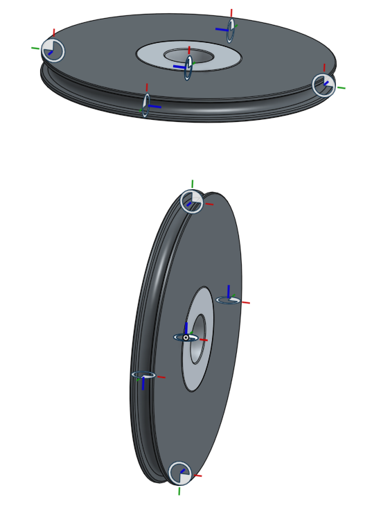
Here is what I have in OnShape (simplified version in an assembly):
In Solidworks, I create an empty part, insert it into the assembly, edit the part in-context of the assembly, make several sketches to define the path, a sketch to define the profile, and perform a sweep. In Solidworks, the features (planes, points, sketches, etc) of my parts/assemblies are made available in-context for use to define coincidence points for the path. When I attempt to do an in-context edit in Onshape, none of the features of my parts/assemblies are made available to reference.
How does one accomplish this in Onshape? Anyone have a video link?
I am trying to create a wire rope routing around two sheaves similar to this screen shot (done in SW):
Here is what I have in OnShape (simplified version in an assembly):
In Solidworks, I create an empty part, insert it into the assembly, edit the part in-context of the assembly, make several sketches to define the path, a sketch to define the profile, and perform a sweep. In Solidworks, the features (planes, points, sketches, etc) of my parts/assemblies are made available in-context for use to define coincidence points for the path. When I attempt to do an in-context edit in Onshape, none of the features of my parts/assemblies are made available to reference.
How does one accomplish this in Onshape? Anyone have a video link?
0
Comments
On the other hand, this looks like a great opportunity for a custom feature, which if done right, can lead to a better workflow (e.g., just select the pulleys in sequence). I might try to give it a shot in the next few days, but someone here might beat me to it
First, Onshape cannot insert a blank "part" (or file) into an assembly - even if I want to mate origin to origin. This is a limitation.
Second, I had to create a separate parts studio for the wire rope. I made a profile (circle) and then extruded it symmetrically 1mm. Now I am able to add it to the assembly and mate it to a mate connector I added to the sheave to represent the wire rope tread (the four mate connectors shown) . Then I edited the wire rope in-context and added individual segments based on their plane (Top and Right in this case). However, all the segments are treated as individual "parts". That's confusing.
Problem: In-Context constraints do not seem to work well. If I adjust the distance between the two sheaves (say 100mm) the wire rope does not rebuild and adjust (lengthen) the top segment as show here:
The tangent-circle-center is defined concentric with the sheave bearing but this constraint is not maintained. This is disappointing. I can't figure out how to solve this problem.
For reference, here is what we design and we need Onshape to ultimately do:
In Solidworks, this assembly is completely flexible. We can move the cylinder, which will move the block, which will raise/lower the platform, and the wire ropes will also adjust accordingly.
The structure is that, like in your last post, you make a bunch of mate connectors where the rope should go, but you also mate identical circular profiles to those mate connectors (you can insert a sketched disk from a part studio into an assembly). Then you create a single rope part in context using the custom feature I just wrote (it's reusable). You can then move the profiles, pulleys, etc. -- the context won't automatically update, but it will with a single right-click on the rope and go to "update context". I'm running off right now but let me know if I can clarify any part of this.
I really hope the Custom Feature (FeatureScript ??) becomes a reality.
I have worked with similar wire designs in Soildworks for many years and I have experienced lots of problems.
As you can see in the image below we have many sheaves. The wire comes from a sheave, entres the next sheave tangentially and exits in the direction of the next sheve, entering again tangentially.
If one sheave is moved all sheaves will move, because the angle of wire in and out changes a little.
I use 3D sketch in an in-context part to achive this. If OnShape if can do this in a simpler way it would be fantastic
Sometimes we need to plan a lift and rigging operation in detail.
When using many chain hoist we come into a similar design situation. If you pull on one hoist, all the others are moving.
Here another situation, many ropes, slings and steel wires in any direction, many related to each other ...
Source: www.conbit.eu
As this topic was written 2 years ago, I'm hoping there is now a way (or workaround) to do this ? Maybe someone has written a script ?
Any feedback appreciated, thanks !