Welcome to the Onshape forum! Ask questions and join in the discussions about everything Onshape.
First time visiting? Here are some places to start:- Looking for a certain topic? Check out the categories filter or use Search (upper right).
- Need support? Ask a question to our Community Support category.
- Please submit support tickets for bugs but you can request improvements in the Product Feedback category.
- Be respectful, on topic and if you see a problem, Flag it.
If you would like to contact our Community Manager personally, feel free to send a private message or an email.
Options
Is there an easy way to perform this tricky mating several times?
 declan_oller
Member Posts: 16 ✭✭
declan_oller
Member Posts: 16 ✭✭
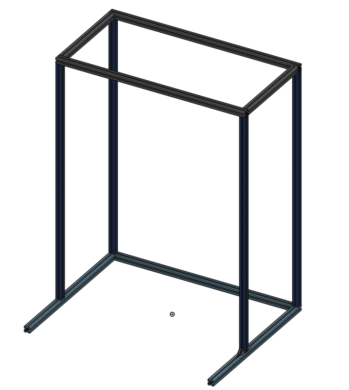
Hi, I've created a cage with aluminum extrusion, using the Beam feature, like so:
I also used the PartCommunity 3D application to get some T-slot nuts and corner brackets like this:
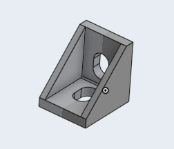
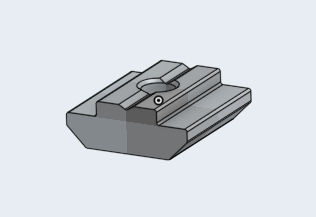
Which are good for the size of my aluminum.
To cut to the chase, here's what I want (and made):
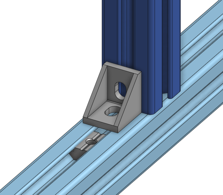
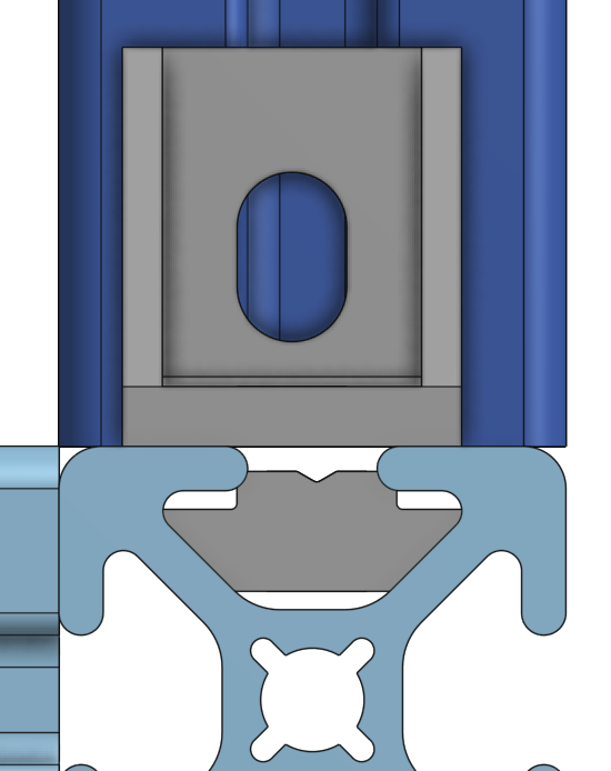
I then managed to get the nut inside the extrusion channel, via a slider mate. This itself was pretty tricky, because it was hard to see and click on the part inside the extrusion (because it's kind of tucked away in there). Then I got the corner bracket to be in the corner, but I had to do a planar mate with the horizontal (light blue) extrusion face, and then another planar mate with the vertical (dark blue) extrusion face.
This too wasn't super easy, and even then it's not super aligned (I know I can adjust it manually, but is there no way to make it automatically center with that face?):
Anyway, my next challenge is doing this for ALL the corners where two extrusions meet. I know I could do it like I did it, but to be honest I kind of struggled with that a little and I'm not loving the idea of doing it another ~15 times.
So my question is, is there some easy way to repeat this?
And, is there some easy way to mate the t-slot nut inside the channel? When I did it, both on the nut and in the channel there were multiple faces I could click, so it took several tries to get the right pair.
Lastly, is there some clever way to mate that corner bracket to the corner, and to make it automatically centered with the faces of those two extrusions?
thanks for any tips!
I also used the PartCommunity 3D application to get some T-slot nuts and corner brackets like this:
Which are good for the size of my aluminum.
To cut to the chase, here's what I want (and made):
I then managed to get the nut inside the extrusion channel, via a slider mate. This itself was pretty tricky, because it was hard to see and click on the part inside the extrusion (because it's kind of tucked away in there). Then I got the corner bracket to be in the corner, but I had to do a planar mate with the horizontal (light blue) extrusion face, and then another planar mate with the vertical (dark blue) extrusion face.
This too wasn't super easy, and even then it's not super aligned (I know I can adjust it manually, but is there no way to make it automatically center with that face?):
Anyway, my next challenge is doing this for ALL the corners where two extrusions meet. I know I could do it like I did it, but to be honest I kind of struggled with that a little and I'm not loving the idea of doing it another ~15 times.
So my question is, is there some easy way to repeat this?
And, is there some easy way to mate the t-slot nut inside the channel? When I did it, both on the nut and in the channel there were multiple faces I could click, so it took several tries to get the right pair.
Lastly, is there some clever way to mate that corner bracket to the corner, and to make it automatically centered with the faces of those two extrusions?
thanks for any tips!
Tagged:
0
Comments
HWM-Water Ltd
Now you might be asking yourself how I got the mate connectors in the middle of the slot as this would help with your problem in the last image. As @owen_sparks said, you should only need one mate for the majority of things here. You will create a mate connector 'between entities' on your 80/20 to make sure the corner bracket is flush to it (I would just use the bottom edge for easy alignment). From there you can do a fasten mate with an offset of the corner bracket height for proper placement.
Feel free to share your document and I'd be happy to set one up with screenshots so you can figure out the rest.
Twitter: @bradleysauln
Here is a similar way of doing what bradley is saying
Set every gap with a central connector:
Then assemble
Link:
https://cad.onshape.com/documents/28050bca2b1ddeb0acbab720/w/72369ffa7faabbf84de28ab1/e/87a170d244e7aeea6332cdf2
HWM-Water Ltd
For example, it looks like this when I try to:
So I can select the origin entity, but after that, I can't select any other point for the between entity one...
Am I using it wrong? The only documentation on between entities mate connectors I can find is a brief mention here, but it doesn't really say how to actually use it.
I did what you said with making a mate connector offset for the t-slot nut, but I did it in the tab from the partscommunity 3D thing, like this:
is that the right idea, or should I be adding that mate connector somewhere else?
Another thing I'm more generally confused about... I guess I don't understand what the purpose of sketches in the parts studio vs assemblies are, i.e., at what complexity stage you built parts and then where you combine them to form an assembly.
For example, following some beams tutorial video, I first made some planes with constraints, and then some sketches in those planes, for the "bottom" of my frame, the top, the front and back, etc, like this:
And then I used the Beams feature to add the beams to the sketches, because it handled the edges nicely (it has that feature to let you trim them where they meet each other), like this:
Is that not the way to do it? For example, would it be better to just create the parts separately, so they can be easily duplicated and stuff, and create their mate connectors in the Parts studio, and then combine them all in the assembly?
Just to be sure, if that's the case, for the different lengths, do I just create a different sketch for each different length segment, and then create a beam out of each of them?
Another thing I'm kind of confused about is the mate between entities. I took a look at john_mcclary's document and I think I've figured it out... is the right way to add those mate connectors in the gaps like this? 1) in the parts studio, create a plane on the face of the extrusion, 2) create a sketch in that plane, 3) create lines bridging those gaps, 4) create mate connectors on those lines?
That seems to be what he's doing here:
thank you again for all the help.
HWM-Water Ltd
https://cad.onshape.com/documents/b8640a77b3f2b4975d7885a0/w/d17a83366ec3cd89b6fd99ff/e/a00dd38e6cadfa5a323b2a6e
I mostly copied the process used in john_mcclary's video, but I'm still confused about a couple things:
1) Since I wanted a few different lengths of extrusion, but all with the mate connectors in the gaps, what I did is create the first one in a parts studio, and then right click on the parts studio tab and duplicate it several times. Then for each one, I changed the length of the sketch line the beam was based on. Is there a better way of doing that, or should I have a separate parts studio for each part? I noticed john_mcclary had several parts in the same parts studio.
2) I got those 14056 and 25-3206 parts from the Partscommunity 3D application, but it's a bit of a pain to locate them. Is there a way I can save those parts locally, to my account, so I can easily find them between different projects/documents?
3) I tried to use the replicate command like you said, but I'm not sure I can here? I thought I could mate one corner of my bracket sub-assy to a mate connector on one of the extrusion part I wanted, and then repeat that by using the corner bracket as the seed entity, and choosing more extrusion mate connectors for it to replicate that mating with, but it didn't seem to work... it seems to need edges or faces, and I guess my mate connector isn't really either of those?
4) this is a total long shot, but I'm looking for a tripod camera mount part (and ideally a dummy DSLR object), do you know if there are any pre defined things like that or just something I should make a mock-up of myself?
thanks again for the help, I've learned a ton here.